background image

Operating instructions

W3G450-ZI07-H1

Translation of the original operating instructions

NOTE
Tightness and strain relief are dependent on the cable
used.

→ This must be checked by the user.

4.3.2 Connecting wires to terminals

WARNING
Live terminals and connections even with device
switched off

Electric shock
→ Wait five minutes after disconnecting the voltage at all poles

before opening the device.

;

Remove the cap from the cable gland.

Only remove caps where cables are fed in.

;

Route the wire(s) (not included in scope of delivery) into the terminal
box.

;

First connect the "PE" (protective earth).

;

Connect the wires to the corresponding terminals.

Use a screwdriver to do so.
When connecting, ensure that no wire ends fan out.

;

Seal the terminal box.

;

Fit the terminal box cover so that the arrow points towards the cable
glands.

4.3.3 Cable routing

Water must be prevented from reaching the cable gland along the cable.

NOTE
Damage caused by moisture penetration.

Moisture can penetrate into the terminal box if water is
constantly present at the cable glands.
→ To prevent the constant accumulation of water at the cable

glands, the cable should be routed in a U-shaped loop
wherever possible.

→ If this is not possible, a drip edge can be produced by

fitting a cable tie directly in front of the cable gland for example.

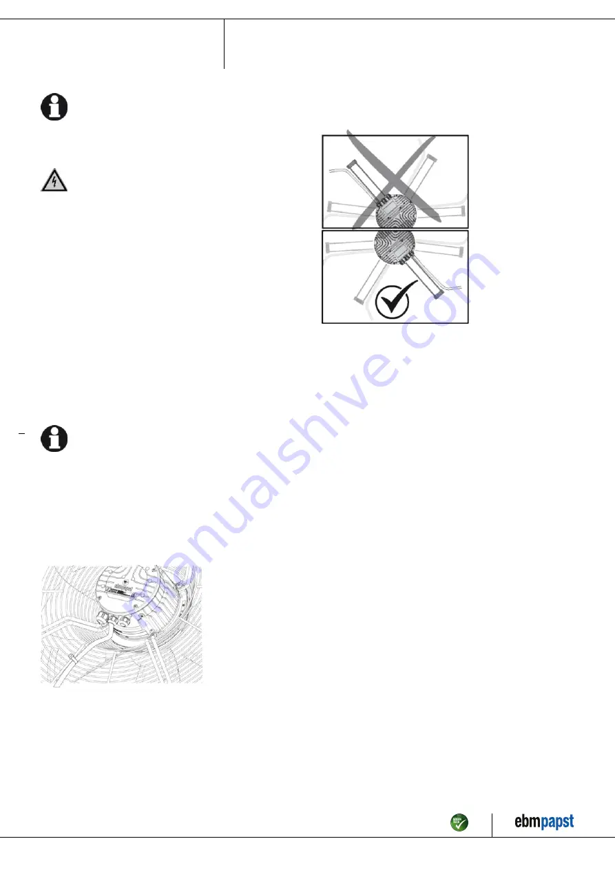
Fans installed lying flat

Make sure the cable is routed in a U-shaped loop.

Fig. 2: Fan installed lying flat, cable routed in a U-shaped loop.

Fans installed upright

When routing the cable, make sure that the cable glands are located at
the bottom. The cables must always be routed downward.

Fig. 3: Cable routing for fans installed upright.

Item no. 57958-5-9970 · ENU · Change 244915 · Approved 2022-01-12 · Page 10 / 14

ebm-papst Mulfingen GmbH & Co. KG · Bachmühle 2 · D-74673 Mulfingen · Phone +49 (0) 7938 81-0 · Fax +49 (0) 7938 81-110 · info1@de.ebmpapst.com · www.ebmpapst.com

Summary of Contents for W3G450-ZI07-H1

Page 1: ...thorized specialists are permitted to install the device to carry out a test run and to perform work on the electrical installation 1 3 Basic safety rules 1 1 3 Basic safety rules The safety hazards a...

Page 2: ...ion appropriate shielding measures have to be taken by the user NOTE Electrical or electromagnetic interference after installing the device in customer equipment Verify that the entire setup is EMC co...

Page 3: ...n particular operating the device in the following ways is prohibited and could be hazardous Operating the device in an unbalanced state e g due to dirt deposits or ice formation Resonant operation op...

Page 4: ...orque 1 8 0 3 Nm use must be made of seal provided Cable diameter min 4 mm max 7 mm tightening torque 1 8 0 3 Nm 4 Tightening torque 1 5 0 2 Nm Accessory part Guard grill 45050 2 4039 with oval head s...

Page 5: ...l dimensions in mm 1 Guard grill 45050 2 4039 2 Oval head screw 60080 7 6201 4x Item no 57958 5 9970 ENU Change 244915 Approved 2022 01 12 Page 5 14 ebm papst Mulfingen GmbH Co KG Bachm hle 2 D 74673...

Page 6: ...ake side mounting on suction nozzle The 6 5 mm holes must be pierced from the underside with a mandrel or similar tool We recommend using M6 cheese head screws with hexagon socket DIN 912 DIN EN ISO 4...

Page 7: ...are used on the installation side the ebm papst evaluation loses its validity the conformity must be confirmed again The product does not fall within the scope of Regulation EU 2019 1781 due to the ex...

Page 8: ...ackaging Blades can bend Carefully remove the device from its packaging by the fan housing Strictly avoid shocks Wear safety shoes and cut resistant safety gloves CAUTION The blades of the impeller co...

Page 9: ...rovided on the device The protective earth terminal is located on the housing and provided with a protective earth symbol and a hole 4 2 2 Reactive currents Because of the EMC filter integrated for co...

Page 10: ...le routing Water must be prevented from reaching the cable gland along the cable NOTE Damage caused by moisture penetration Moisture can penetrate into the terminal box if water is constantly present...

Page 11: ...ntact common connection contact rating 250 VAC 2 A AC1 min 10 mA basic insulation on supply side and reinforced insulation on control interface side 8 GND Reference ground for control interface SELV 9...

Page 12: ...witching off the device for maintenance Switch off the device via the control input Do not switch the motor e g in cyclic operation on and off via power supply Disconnect the device from the power sup...

Page 13: ...ning agents used If severe corrosion is visible on load bearing or rotating parts switch off the device immediately and replace it Repair of load bearing or rotating parts is not permitted Operate the...

Page 14: ...nts could drop off during disassembly This can result in fatal or serious injury and material damage Secure components before unfastening to stop them falling 6 3 3 Component disposal The products are...

Reviews: