background image

Operating instructions
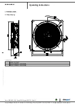
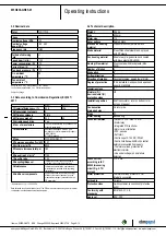
W3G630-GR85-01

Translation of the original operating instructions

4.6 Checking connections

;

Ensure isolation from supply (all phases).

;

Make sure a restart is impossible

;

Check the cables for proper fit.

4.7 Switching on the device

The device may only be switched on if it has been installed properly and
in accordance with its intended use, including the required safety
mechanisms and professional electrical hookup. This also applies for
devices which have already been equipped with plugs and terminals or
similar connectors by the customer.

WARNING
Hot motor housing

Risk of fire
→ Ensure that no combustible or flammable materials are

located close to the fan.

;

Before switching on, check the device for visible external damage
and make sure the protective devices are functional.

;

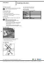
Check the fan's air flow paths for foreign matter and remove any
foreign matter found.

;

Apply the nominal supply voltage.

;

Start the device by changing the input signal.

NOTE
Damage to the device from vibration

Bearing damage, shorter service life
→ Low-vibration operation of the fan must be ensured over the

entire speed control range.

→ Severe vibration can arise for instance from inexpert

handling, transportation damage and resultant imbalance or
be caused by component or structural resonance.

→ Speed ranges with excessively high vibration levels and

possibly resonant frequencies must be determined in the
course of fan commissioning.

→ Either run through the resonant range as quickly as

possible with speed control or find another remedy.

→ Operation with excessively high vibration levels can

lead to premature failure.

4.8 Switching off the device

Switching off the device during operation:

;

Switch off the device via the control input.

;

Do not switch the motor (e.g. in cyclic operation) on and off via power
supply.

Switching off the device for maintenance:

;

Switch off the device via the control input.

;

Do not switch the motor (e.g. in cyclic operation) on and off via power
supply.

;

Disconnect the device from the power supply.

;

When disconnecting, be sure to disconnect the ground connection last.

5. INTEGRATED PROTECTIVE FEATURES

The integrated protective functions cause the motor to switch off
automatically in the event of the faults described in the table.

Fault

Safety feature description/
function

Rotor position detection error

An automatic restart follows.

Blocked rotor

;

After the blockage is

removed, the motor restarts
automatically.

Line undervoltage (line voltage
outside of permitted nominal
voltage range)

;

If the line voltage returns to

permitted values, the motor
restarts automatically.

Phase failure

A phase of the supply voltage
fails for at least 5 s.

;

When all phases are

correctly supplied again, the
motor automatically restarts after
10-40 s.

6. MAINTENANCE, MALFUNCTIONS, POSSIBLE
CAUSES AND REMEDIES

Do not perform any repairs on your device. Send the device to ebm-
papst for repair or replacement.

WARNING
Live terminals and connections even with device
switched off

Electric shock
→ Wait five minutes after disconnecting the voltage at all poles

before opening the device.

CAUTION
If control voltage or a stored speed set value is applied,
the motor will restart automatically, e.g. after a power
failure.

Risk of injury
→ Keep out of the device’s danger zone.
→ When working on the device, switch off the line voltage

and ensure that it cannot be switched back on.

→ Wait until the device comes to a stop.
→ After working on the device, remove any tools or other

objects from the device.

NOTE

If the device is not operated for a lengthy period in installed
condition in a dry environment, it is to be started up and
operated at full speed for one hour at least every four months. If
the device is not operated for a lengthy period in installed
condition in a damp environment (e.g. outdoors), it is to be
started up and operated at full speed for at least two hours once
a month to move the bearings and allow any condensate that
may have ingressed to evaporate.

Malfunction/fault

Possible cause

Possible remedy

Item no. 50329-5-9970 · ENU · Change 205336 · Approved 2020-07-16 · Page 10 / 12

ebm-papst Mulfingen GmbH & Co. KG · Bachmühle 2 · D-74673 Mulfingen · Phone +49 (0) 7938 81-0 · Fax +49 (0) 7938 81-110 · info1@de.ebmpapst.com · www.ebmpapst.com

Summary of Contents for W3G630-GR85-01

Page 1: ...d specialists are permitted to install the device to carry out a test run and to perform work on the electrical installation 1 3 Basic safety rules 1 1 3 Basic safety rules The safety hazards associated with the device must be assessed again following installation in the final product The locally applicable industrial safety regulations are always to be observed when working on the device Keep the...

Page 2: ... g in conjunction with open and closed loop control devices If impermissible radiation levels occur following installation appropriate shielding measures have to be taken by the user NOTE Electrical or electromagnetic interference after installing the device in customer equipment Verify that the entire setup is EMC compliant 1 7 Mechanical movement DANGER Rotating device Risk of injury to body par...

Page 3: ...work Conveying air at an ambient air pressure between 800 mbar and 1050 mbar Using the device within the permitted ambient temperature range see Chapter 3 6 Transport and storage conditions and Chapter 3 2 Nominal data Operating the device with all protective devices Following the operating instructions Improper use In particular operating the device in the following ways is prohibited and could b...

Page 4: ... dimensions in mm 1 Direction of air flow V 2 Cable PVC AWG18 6x crimped ferrules 3 Cable PVC AWG22 4x crimped ferrules Item no 50329 5 9970 ENU Change 205336 Approved 2020 07 16 Page 4 12 ebm papst Mulfingen GmbH Co KG Bachmühle 2 D 74673 Mulfingen Phone 49 0 7938 81 0 Fax 49 0 7938 81 110 info1 de ebmpapst com www ebmpapst com ...

Page 5: ...ficiency level The ErP data is determined using a motor impeller combination in a standardized measurement setup 3 4 Technical description Weight 25 4 kg Size 630 mm Motor size 112 Rotor surface Painted black Electronics housing material Die cast aluminum painted black Blade material Press fitted sheet steel blank sprayed with PP plastic Fan housing material Sheet steel pre galvanized and coated w...

Page 6: ...the arrangement It is the responsibility of the installation engineer or operator owner of the device to ensure if necessary after consultation with the network operator that this device is only connected to a connection point with a Ssc value that is greater than or equal to 120 times the rated output of the arrangement 4 CONNECTION AND STARTUP 4 1 Mechanical connection CAUTION Cutting and crushi...

Page 7: ...e with the resistance specifications according to EN 61800 5 1 for the protective earth connection circuit must be verified in the end application Depending on the installation situation it may be necessary to connect an additional protective earth conductor by way of the extra protective earth terminal provided on the device The protective earth terminal is located on the housing and provided wit...

Page 8: ... cable should be routed in a U shaped loop wherever possible If this is not possible a drip edge can be produced by fitting a cable tie directly in front of the cable gland for example Fans installed lying flat Fig 1 Fan installed lying flat cable routed in a U shaped loop Make sure the cable is routed in a U shaped loop Avoid kinks or bends in the bushing Fans installed upright Fig 2 Cable routin...

Page 9: ...250 VAC min 10 mA AC1 1 7 NC white 2 Floating status contact break for failure 2 8 0 10 V yellow Control input set value 0 10 VDC impedance 100 kOhm SELV 2 11 10 V red Voltage output 10 VDC 3 max 10 mA power supply for external devices e g potentiometers SELV 2 12 GND blue Reference ground for control interface SELV Item no 50329 5 9970 ENU Change 205336 Approved 2020 07 16 Page 9 12 ebm papst Mul...

Page 10: ...power supply When disconnecting be sure to disconnect the ground connection last 5 INTEGRATED PROTECTIVE FEATURES The integrated protective functions cause the motor to switch off automatically in the event of the faults described in the table Fault Safety feature description function Rotor position detection error An automatic restart follows Blocked rotor After the blockage is removed the motor ...

Page 11: ...eaning To ensure a long service life check the fans regularly for proper operation and soiling The frequency of checking is to be adapted accordingly depending on the degree of soiling DANGER Risk of injury from rotating fan Only clean when not in motion Do not disconnect the fan from the power supply just switch it off via the control input This will prevent start up of the fan Dirt deposits on t...

Page 12: ...ations with regard to the disposal of products or waste occurring in the various phases of the life cycle The corresponding disposal standards are also to be heeded 6 3 2 Disassembly Disassembly of the product must be performed or supervised by qualified personnel with the appropriate technical knowledge The product is to be disassembled into suitable components for disposal employing standard pro...

Reviews: