
Operating instructions
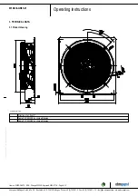
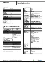
W3G630-GR85-01
Translation of the original operating instructions
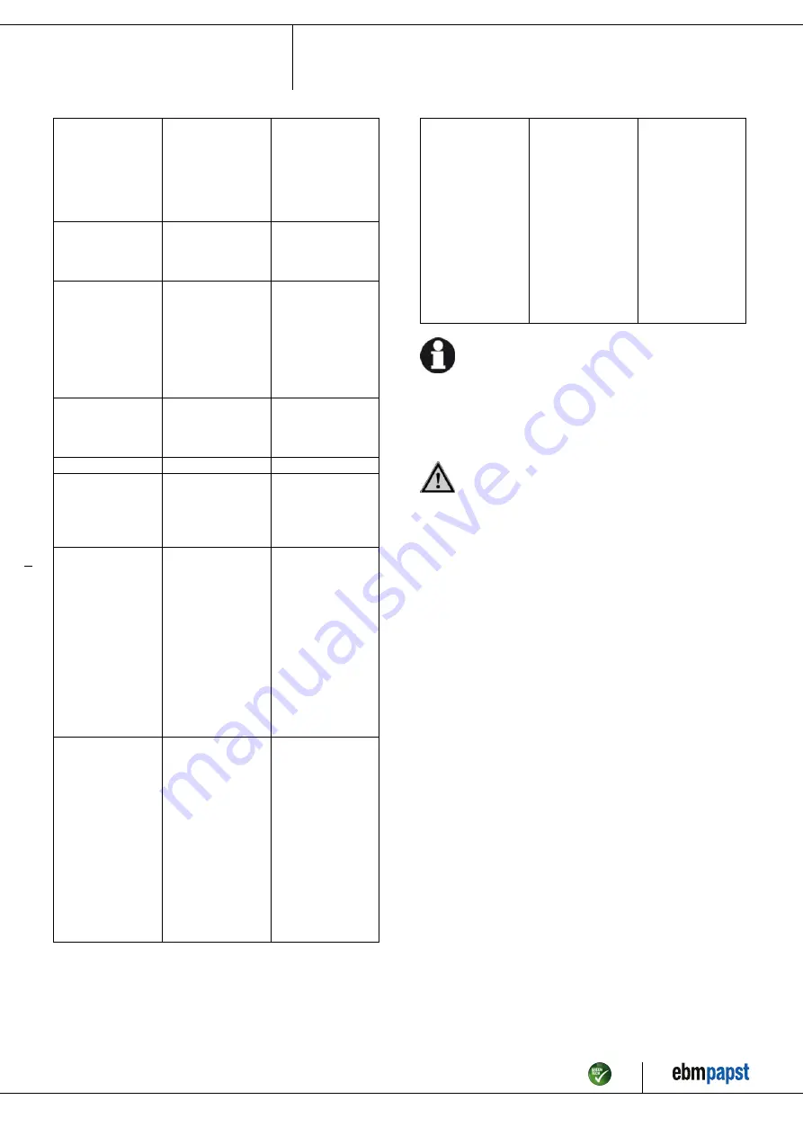
Impeller not
running smoothly
Imbalance in rotating
parts
Clean the device;
replace it if imbalance
persists after cleaning.
Make sure no
weight clips are
removed during
cleaning.
Motor not turning
Mechanical blockage
Switch off, isolate
from supply and
remove mechanical
blockage.
Line voltage faulty
Check line voltage,
restore power supply.
Attention! The error
message resets
automatically.
Device restarts
automatically without
warning.
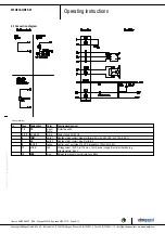
Faulty connection
Isolate from supply,
correct connection;
see connection
diagram.
Broken motor winding Replace device
Thermal overload
protector activated
Allow motor to cool
off, locate and rectify
cause of error,
release restart lockout
if necessary
Deficient cooling
Improve cooling. Let
the device cool down.
To reset the error
message, switch off
the line voltage for at
least 25 s and then
switch it on again.
Alternatively, reset
the error message by
applying a control
signal of < 0.5 V to
Din1 or by shorting
Din1 to GND.
Ambient temperature
too high
Reduce the ambient
temperature. Let the
device cool down.
To reset the error
message, switch off
the line voltage for at
least 25 s and then
switch it on again.
Alternatively, reset
the error message by
applying a control
signal of < 0.5 V to
Din1 or by shorting
Din1 to GND.
Impermissible point of
operation (e.g. back
pressure too high)
Correct the operating
point. Let the device
cool down.
To reset the error
message, switch off
the line voltage for at
least 25 s and then
switch it on again.
Alternatively, reset
the error message by
applying a control
signal of < 0.5 V to
Din1 or by shorting
Din1 to GND.
In the event of further malfunctions, contact ebm-papst.
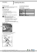
6.1 Cleaning
To ensure a long service life, check the fans regularly for proper
operation and soiling. The frequency of checking is to be adapted
accordingly depending on the degree of soiling.
DANGER
Risk of injury from rotating fan.
→ Only clean when not in motion. Do not disconnect the fan
from the power supply, just switch it off via the control input.
This will prevent start-up of the fan.
;
Dirt deposits on the motor housing can cause overheating of the motor.
;
Soiling of the impeller can cause vibration that will shorten the service
life of the fan.
;
Severe vibration can destroy the fan.
;
In such cases, switch off the fan immediately and clean it.
;
The preferred method of cleaning is dry cleaning, e.g. using
compressed air.
;
Do not use aggressive cleaning agents!
NOTE
Damage to the device during cleaning
Malfunction possible
→ Do not clean the device using a water jet or high-pressure
cleaner.
→ Do not use any acid, alkali or solvent-basedcleaning
agents.
→ Do not use any pointed or sharp-edged objects for cleaning
;
Completely remove any cleaning agents used.
;
If severe corrosion is visible on load-bearing or rotating parts, switch
off the device immediately and replace it.
;
Repair of load-bearing or rotating parts is not permitted!
;
Operate the fan for 2 hours at maximum speed so that any water that
has ingressed can evaporate.
;
If cleaning does not eliminate vibrations, the fan may need to be
rebalanced. To have it rebalanced, contact ebm-papst.
;
The fan is equipped with maintenance-free ball bearings. The lifetime
lubrication of the ball bearings is designed for a service life of 40,000
hours.
;
If bearing replacement is necessary after that period, contact ebm-
papst.
;
Adapt the maintenance intervals to the actual level of dust exposure.
Item no. 50329-5-9970 · ENU · Change 205336 · Approved 2020-07-16 · Page 11 / 12
ebm-papst Mulfingen GmbH & Co. KG · Bachmühle 2 · D-74673 Mulfingen · Phone +49 (0) 7938 81-0 · Fax +49 (0) 7938 81-110 · info1@de.ebmpapst.com · www.ebmpapst.com


