
Operating instructions
W3G630-GR85-01
Translation of the original operating instructions
With regard to cyclic speed loads, note that the rotating parts of
the device are designed for a maximum of one million load
cycles. If you have special questions, consult ebm-papst for
support.
;
Use the device in accordance with its degree of protection.
Information on surface quality
The surfaces of the products conform to the generally applicable industrial
standard. The surface quality may change during the production period.
This has no effect on strength, dimensional stability and dimensional
accuracy.
The color pigments in the paints used perceptibly react to UV light over
the course of time. This does not however in any way affect the
technical properties of the products. The product is to be protected against
UV radiation to prevent the formation of patches and fading. Changes in
color are not a reason for complaint and are not covered by the warranty.
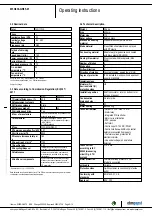
3.5 Mounting data
Strength class of
screws
8.8
;
Secure the screws against unintentional loosening (e.g. use self-
locking screws).
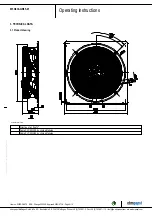
For screw clearance, see Chapter 3.1 Product drawing
Any further mounting data required can be taken from the product
drawing or Section Chapter 4.1 Mechanical connection.
3.6 Transport and storage conditions
Max. permitted
ambient temp. for
motor (transport/
storage)
+ 80 °C
Min. permitted
ambient temp. for
motor (transport/
storage)
- 40 °C
3.7 Electromagnetic compatibility
EMC immunity to
interference
According to EN 61000-6-2 (industrial
environment)
EMC circuit feedback
According to EN 61000-3-2/3
EMC interference
emission
According to EN 55022 (Class B,
household environment)
If several devices are switched in parallel on the supply side
so that the line current of the arrangement is in the range of 16-
75 A, then this arrangement conforms to IEC 61000-3-12
provided that the short-circuit power S
sc
at the connection point
of the customer system to the public power system is greater
than or equal to 120 times the rated output of the arrangement.
It is the responsibility of the installation engineer or operator/
owner of the device to ensure, if necessary after consultation
with the network operator, that this device is only connected to
a connection point with a S
sc
value that is greater than or equal
to 120 times the rated output of the arrangement.
4. CONNECTION AND STARTUP
4.1 Mechanical connection
CAUTION
Cutting and crushing hazard when removing device
from packaging
Blades can bend
→ Carefully remove the device from its packaging, by the fan
housing. Strictly avoid shocks.
→ Wear safety shoes and cut-resistant safety gloves.
CAUTION
Device weighs over 25 kg! Heavy load when unpacking
device.
Risk of physical injury, such as back injuries.
→ Use suitable hoisting equipment to remove the device from
its packaging.
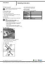
CAUTION
The blades of the impeller could be damaged.
→ Carefully set down the fan on a soft surface. Make sure the
blades are not subjected to load.
→ Following installation, make sure the impeller moves
easily and that the blades of the impeller are not deformed or
bent and do not catch at any point.
NOTE
Damage to the device from vibration
Bearing damage, shorter service life
→ The fan must not be subjected to force or excessive vibration
from sections of the installation.
→ If the fan is connected to air ducts, the connection should
be isolated from vibration, e.g. using compensators or similar
elements.
→ Ensure stress-free attachment of the fan to the
substructure.
;
Check the device for transport damage. Damaged devices are not to
be installed.
;
Install the undamaged device in accordance with your application.
CAUTION
Possible damage to the device
If the device slips during installation, serious damage can result.
→ Ensure that the device is securely positioned at its place of
installation until all fastening screws have been tightened.
●
The fan must not be strained on fastening.
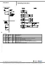
4.2 Electrical connection
DANGER
Voltage on the device
Electric shock
→ Always connect a protective earth first.
→ Check the protective earth.
Item no. 50329-5-9970 · ENU · Change 205336 · Approved 2020-07-16 · Page 6 / 12
ebm-papst Mulfingen GmbH & Co. KG · Bachmühle 2 · D-74673 Mulfingen · Phone +49 (0) 7938 81-0 · Fax +49 (0) 7938 81-110 · info1@de.ebmpapst.com · www.ebmpapst.com


