


Operating instructions
W3G800-KU21-D1
Translation of the original operating instructions
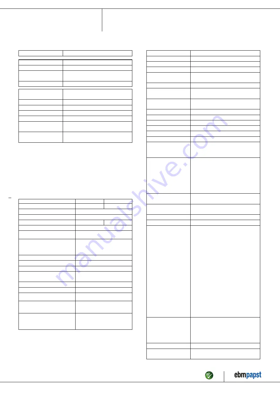
3.2 Nominal data
Motor
M3G150-IF
Phase
3~
Nominal voltage / VAC
400
Nominal voltage
range / VAC
380 .. 480
Frequency / Hz
50/60
Method of obtaining
data
ml
Speed (rpm) / min
-1
1080
Power consumption / W
2900
Current draw / A
4.4
Max. back pressure / Pa
300
Min. ambient
temperature / °C
-40
Max. ambient
temperature / °C
60
ml = Max. load · me = Max. efficiency · fa = Free air
cs = Customer specification · ce = Customer equipment
Subject to change
Occasional start-up at temperatures between -40 °C and -25 °C is
permitted. For continuous operation at ambient temperatures below -25
°C (such as refrigeration applications), a fan design with special low-
temperature bearings must be used.
3.3 Data according to Commission Regulation (EU) 327/
2011
Actual
Req. 2015
01 Overall efficiency η
es
/ %
50.8
36.4
02 Measurement category
A
03 Efficiency category
Static
04 Efficiency grade N
54.4
40
05 Variable speed drive
Yes
06 Year of manufacture
The year of manufacture is specified on the
product's rating label.
07 Manufacturer
ebm-papst Mulfingen GmbH & Co. KG
Amtsgericht (court of registration) Stuttgart ·
HRA 590344
D-74673 Mulfingen
08 Type
W3G800-KU21-D1
09 Power consumption P
ed
/ kW
2.67
09 Air flow q
v
/ m³/h
19095
09 Pressure increase total p
fs
/
Pa
243
10 Speed (rpm) n / min
-1
1085
11 Specific ratio
*
1.00
12 Recycling/disposal
Information on recycling and disposal is
provided in the operating instructions.
13 Maintenance
Information on installation, operation and
maintenance is provided in the operating
instructions.
14 Additional components
Components used to calculate the energy
efficiency that are not apparent from the
measurement category are detailed in the
CE declaration.
*
Specific ratio = 1 + p
fs
/ 100 000 Pa
Data obtained at optimum efficiency level. The ErP data is determined using a motor-impeller
combination in a standardized measurement setup.
3.4 Technical description
Weight
50 kg
Size
800 mm
Motor size
150
Rotor surface
Painted black
Electronics housing
material
Die-cast aluminum, painted gray
Impeller material
PP plastic
Fan housing material
Sheet steel, galvanized and coated with
black plastic (RAL 9005)
Guard grille material
Steel, coated with black plastic (RAL
9005)
Number of blades
5
Blade pitch
0°
Airflow direction
V
Direction of rotation
Clockwise, viewed toward rotor
Degree of protection
IP55
Insulation class
"F"
Moisture (F) /
Environmental (H)
protection class
H2
Ambient temperature
note
Occasional start-up at temperatures
between -40°C and -25°C is permitted.
For continuous operation at ambient
temperatures below -25°C (such as
refrigeration applications), use must be
made of a fan design with special low-
temperature bearings.
Installation position
Shaft horizontal or rotor on bottom; rotor
on top on request
Condensation
drainage holes
On rotor side
Mode
S1
Motor bearing
Ball bearing
Technical features
- Operation and alarm display with LED
- External 15-50 VDC input
(parameterization)
- Alarm relay
- Integrated PI controller
- Configurable inputs/outputs (I/O)
- MODBUS V6.3
- Motor current limitation
- RS-485 MODBUS-RTU
- Soft start
- Voltage output 3.3-24 VDC, Pmax =
800 mW
- Control interface with SELV potential
safely disconnected from the mains
- Thermal overload protection for
electronics/motor
- Line undervoltage / phase failure
detection
Touch current
according to IEC
60990 (measuring
circuit Fig. 4, TN
system)
<= 3.5 mA
Electrical hookup
Terminal box
Motor protection
Reverse polarity and locked-rotor
protection
Item no. 56589-5-9970 · ENU · Change 209539 · Approved 2021-02-01 · Page 5 / 16
ebm-papst Mulfingen GmbH & Co. KG · Bachmühle 2 · D-74673 Mulfingen · Phone +49 (0) 7938 81-0 · Fax +49 (0) 7938 81-110 · info1@de.ebmpapst.com · www.ebmpapst.com


