background image

Operating instructions

W3G800-KU21-D1

Translation of the original operating instructions

4.2.6 Locked-rotor protection

Due to the locked-rotor protection, the starting current (LRA) is
equal to or less than the nominal current (FLA).

4.3 Connection in terminal box

4.3.1 Preparing cables for connection

NOTE
Care must be taken to avoid damaging the paintwork of
the terminal box if the cable glands are replaced.

This could lead to corrosion and leakage!

Only strip the cable as far as necessary, ensuring that the cable gland is
sealed and there is no strain on the connections. For tightening torques,
see Chapter 3.1 Product drawing.

NOTE
Tightness and strain relief are dependent on the cable
used.

→ This must be checked by the user.

Fig. 1: Recommended stripped lengths in mm (inside terminal box)

4.3.2 Connect cables to terminals

WARNING
Live terminals and connections even with device
switched off

Electric shock
→ Wait five minutes after disconnecting the voltage at all poles

before opening the device.

;

Open the terminal box.

;

Remove the cap from the cable gland.

;

Only remove caps where cables are fed in.

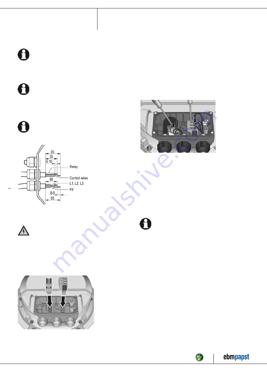
Fig. 2: Fit the connectors in the terminal box

;

Fit the cable glands with the seals provided in the terminal box.

;

Route the cable(s) (not included in the scope of delivery) into the
terminal box.

;

Ensure separate routing of the supply cable(s) and the cables for
status contact and control interface. Depending on the requirements for
the end device, the physical separation of these cables in the terminal
box may be mandatory. Use the partitions inside the terminal box as
an aid to routing for this purpose.

;

First connect the protective earth "PE".

;

Connect the cables to the corresponding terminals. Use a
screwdriver to do so. When connecting, make sure the wires do not
splay out. Insert the strands until they meet with resistance.

Fig. 3: Connection of cables at terminals

;

There must not be any tensile stress between the terminal and the
cable gland. The cable must be provided with strain relief.

;

The cable glands must be tight.

;

Fit the terminal box cover, making sure that the sealing surfaces are
clean.

;

Screw in the four screws (for tightening torque, see Chapter 3.1
Product drawing).

4.3.3 Cable routing

Water must be prevented from reaching the cable gland along the cable.

NOTE
Damage caused by moisture penetration.

Moisture can penetrate into the terminal box if water is
constantly present at the cable glands.
→ To prevent the constant accumulation of water at the cable

glands, the cable should be routed in a U-shaped loop
wherever possible.

→ If this is not possible, a drip edge can be produced by

fitting a cable tie directly in front of the cable gland for example.

Fans installed lying flat

Make sure the cable is routed in a U-shaped loop.

Fans installed upright

When routing the cable, make sure that the cable glands are located at
the bottom. The cables must always be routed downward.

Item no. 56589-5-9970 · ENU · Change 209539 · Approved 2021-02-01 · Page 8 / 16

ebm-papst Mulfingen GmbH & Co. KG · Bachmühle 2 · D-74673 Mulfingen · Phone +49 (0) 7938 81-0 · Fax +49 (0) 7938 81-110 · info1@de.ebmpapst.com · www.ebmpapst.com

Summary of Contents for W3G800-KU21-D1

Page 1: ...o carry out a test run and to perform work on the electrical installation 1 3 Basic safety rules 1 1 3 Basic safety rules The safety hazards associated with the device must be assessed again following...

Page 2: ...g in conjunction with open and closed loop control devices If impermissible radiation levels occur following installation appropriate shielding measures have to be taken by the user NOTE Electrical or...

Page 3: ...stationary systems Performing all maintenance work Conveying air at an ambient air pressure between 800 mbar and 1050 mbar Using the device within the permitted ambient temperature range see Chapter...

Page 4: ...flow direction V 2 Cable diameter min 6 mm max 12 mm tightening torque 4 0 6 Nm 3 Tightening torque 3 5 0 5 Nm 4 Mounting holes for FlowGrid Item no 56589 5 9970 ENU Change 209539 Approved 2021 02 01...

Page 5: ...100 000 Pa Data obtained at optimum efficiency level The ErP data is determined using a motor impeller combination in a standardized measurement setup 3 4 Technical description Weight 50 kg Size 800...

Page 6: ...t of the customer system to the public power grid is greater than or equal to 250 times the rated output of the arrangement It is the responsibility of the installation engineer or operator owner of t...

Page 7: ...with the resistance specifications according to EN 61800 5 1 for the protective earth connection circuit must be verified in the end application Depending on the installation situation it may be neces...

Page 8: ...ysical separation of these cables in the terminal box may be mandatory Use the partitions inside the terminal box as an aid to routing for this purpose First connect the protective earth PE Connect th...

Page 9: ...Fan device address 01 Max PWM 100 Min PWM 5 Save set value to EEPROM Yes Set value requirement Analog linear Direction of action parameter set 1 Positive heating Direction of action parameter set 2 Po...

Page 10: ...eristic curve P1 IN SELV CON2 IO3 Function parameterizable see Optional interface functions table Factory setting Analog output 0 10 V max 5 mA function Fan modulation level Characteristic curve param...

Page 11: ...159 0 Ain2 0 10V PWM analog input D159 2 Ri 100K characteristic curve parameterizable f PWM 1k 10KHz SELV Ain2 4 20mA analog input Ri 125R characteristic curve parameterizable SELV D159 3 Din3 active...

Page 12: ...operating instructions 4 7 Equivalent circuit diagrams Item no 56589 5 9970 ENU Change 209539 Approved 2021 02 01 Page 12 16 ebm papst Mulfingen GmbH Co KG Bachm hle 2 D 74673 Mulfingen Phone 49 0 793...

Page 13: ...supply Switching off the device for maintenance Switch off the device via the control input Do not switch the motor e g in cyclic operation on and off via power supply Disconnect the device from the p...

Page 14: ...us LED orange Message at status relay 1 Current limitation in action 2 Line impedance too high DC link voltage unstable 3 Power limiter in action 4 Output stage temperature high 5 Motor temperature hi...

Page 15: ...ls to the actual level of dust exposure 6 3 Safety inspection NOTE High voltage test The integrated EMC filter has Y capacitors The tripping current is exceeded when AC testing voltage is applied Test...

Page 16: ...num Non ferrous metal e g motor windings Plastics particularly with brominated flame retardants in accordance with marking Insulating materials Cables and wires Electronic scrap e g circuit boards Onl...

Reviews: