


Operating instructions
W3G800-NB86-43
Translation of the original operating instructions
3. TECHNICAL DATA
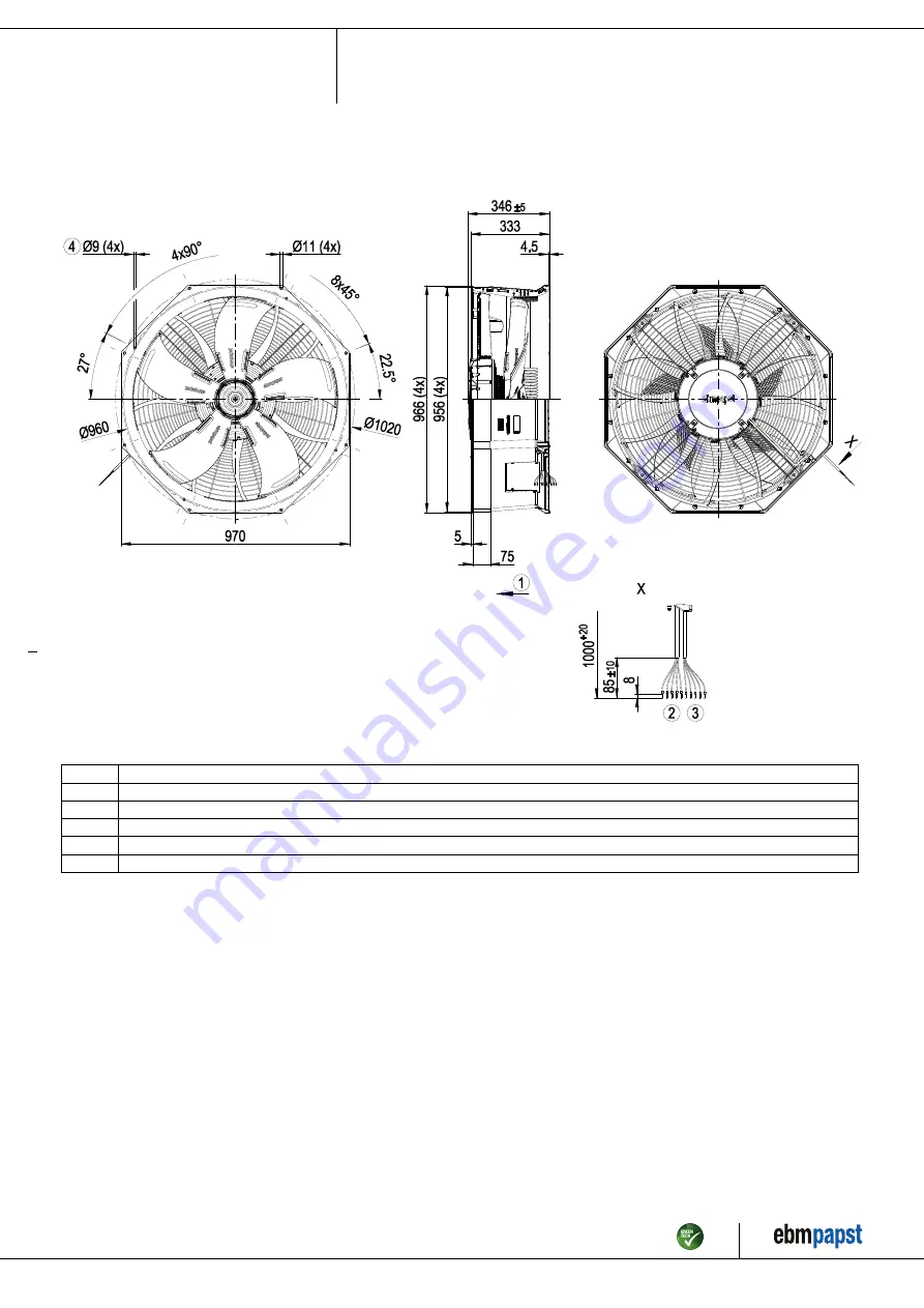
3.1 Product drawing
All dimensions in mm.
1
Airflow direction "V"
2
Cable PVC AWG18
5x wire-end ferrule
3
Cable PVC AWG22
5x wire-end ferrule
4
Mounting holes for FlowGrid
Item no. 55755-5-9970 · ENU · Change 205336 · Approved 2020-07-16 · Page 4 / 13
ebm-papst Mulfingen GmbH & Co. KG · Bachmühle 2 · D-74673 Mulfingen · Phone +49 (0) 7938 81-0 · Fax +49 (0) 7938 81-110 · info1@de.ebmpapst.com · www.ebmpapst.com


