background image

Operating instructions

W3G800-NS26-71

Translation of the original operating instructions

All dimensions in mm.
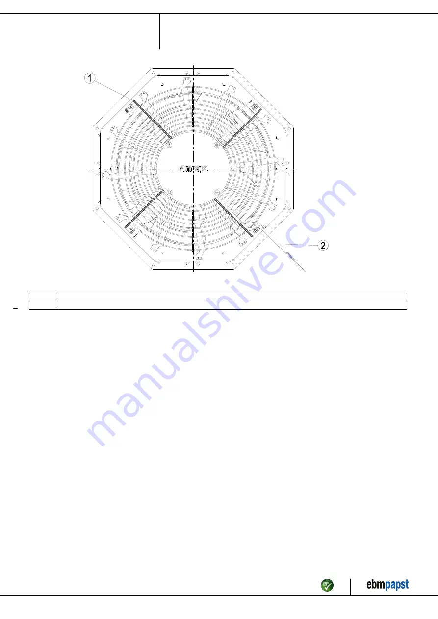
1

Installation position: Shaft horizontal (install support struts only in X-position as illustrated) or rotor on bottom

2

For horizontal shaft installation position, the cable exit must be at the bottom right.

Item no. 55311-5-9970 · ENU · Change 209539 · Approved 2021-02-09 · Page 5 / 14

ebm-papst Mulfingen GmbH & Co. KG · Bachmühle 2 · D-74673 Mulfingen · Phone +49 (0) 7938 81-0 · Fax +49 (0) 7938 81-110 · info1@de.ebmpapst.com · www.ebmpapst.com

Summary of Contents for W3G800-NS26-71

Page 1: ...install the device to carry out a test run and to perform work on the electrical installation 1 3 Basic safety rules 1 1 3 Basic safety rules The safety hazards associated with the device must be ass...

Page 2: ...g in conjunction with open and closed loop control devices If impermissible radiation levels occur following installation appropriate shielding measures have to be taken by the user NOTE Electrical or...

Page 3: ...ork Conveying air at an ambient air pressure between 800 mbar and 1050 mbar Using the device within the permitted ambient temperature range see Chapter 3 6 Transport and storage conditions and Chapter...

Page 4: ...rflow direction V 2 Cable silicone 8x0 5 mm 8x crimped ferrules 3 Cable silicone 4G 1 5 mm 4x crimped ferrules 4 Mounting holes for FlowGrid Item no 55311 5 9970 ENU Change 209539 Approved 2021 02 09...

Page 5: ...ort struts only in X position as illustrated or rotor on bottom 2 For horizontal shaft installation position the cable exit must be at the bottom right Item no 55311 5 9970 ENU Change 209539 Approved...

Page 6: ...ent setup 3 4 Technical description Weight 39 2 kg Size 800 mm Motor size 150 Rotor surface Painted black Electronics housing material Die cast aluminum painted black Blade material PP plastic Fan hou...

Page 7: ...heating tape has only basic insulation The heating tape may only be used with a closed fan housing cover to prevent heat losses and contact with live parts 3 7 2 AxiCool drip pan A heated drip pan tha...

Page 8: ...tightening torque recommended by ebm papst must be checked in the application concerned 4 2 Electrical connection DANGER Voltage on the device Electric shock Always connect a protective earth first Ch...

Page 9: ...l current devices cannot provide personal safety while operating the device When the device power supply is switched on pulsed charging currents from the capacitors in the integrated EMC filter can le...

Page 10: ...tatus contact break for failure contact rating 250 VAC max 2 A AC1 min 10 mA KL 2 7 Din1 green Digital input 1 enable electronics Enable Pin open or applied voltage 5 50 VDC Disable Bridge to GND or a...

Page 11: ...ranges with excessively high vibration levels and possibly resonant frequencies must be determined in the course of fan commissioning Either run through the resonant range as quickly as possible with...

Page 12: ...ically without warning Faulty connection Isolate from supply correct connection see connection diagram Broken motor winding Replace device Deficient cooling Improve cooling Let the device cool down To...

Page 13: ...rotection and resource preservation are top priority corporate goals ebm papst operates an environmental management system which is certified in accordance with ISO 14001 and rigorously implemented ar...

Page 14: ...ploying the proper procedures for electronic scrap Please contact ebm papst for any other questions on disposal Item no 55311 5 9970 ENU Change 209539 Approved 2021 02 09 Page 14 14 ebm papst Mulfinge...

Reviews: