


Operating instructions
W3G910-LU25-D1
Translation of the original operating instructions
Electrical hookup
Terminal box
Motor protection
Reverse polarity and locked-rotor
protection
Protection class
I (with customer connection of protective
earth)
Conformity with
standards
EN 61800-5-1; CE
Approval
UL 1004-7 + 60730-1; EAC; CSA
C22.2 No. 77 + CAN/CSA-E60730-1
With regard to cyclic speed loads, note that the rotating parts of
the device are designed for a maximum of one million load
cycles. If you have special questions, consult ebm-papst for
support.
Information on surface quality
;
Use the device in accordance with its degree of protection.
The surfaces of the products conform to the generally applicable industrial
standard. The surface quality may change during the production period.
This has no effect on strength, dimensional stability and dimensional
accuracy.
The color pigments in the paints used perceptibly react to UV light over
the course of time. The product is to be protected against UV radiation to
prevent the formation of patches and fading. Changes in color are not a
reason for complaint and are not covered by the warranty. UV radiation
in the frequency range and the intensity of natural solar radiation has no
effect on the technical properties of the products.
3.5 Mounting data
Any further mounting data required can be taken from the product
drawing or Section Chapter 4.1 Mechanical connection.
Strength class of
screws
8.8
;
Secure the screws against unintentional loosening (e.g. use self-
locking screws).
3.6 Transport and storage conditions
Max. permitted
ambient temp. for
motor (transport/
storage)
+80 °C
Min. permitted
ambient temp. for
motor (transport/
storage)
-40 °C
3.7 Electromagnetic compatibility
EMC immunity to
interference
According to EN 61000-6-2 (industrial
environment)
EMC interference
emission
According to EN 61000-6-3 (household
environment), except EN 61000-3-2 for
professionally used equipment with a
total rated power greater than 1 kW
If several devices are connected in parallel on the supply side
so that the line current of the arrangement is in the range 16 - 75
A, this arrangement conforms to IEC 61000-3-12, provided that
the short-circuit power S
sc at the connection point of the
customer system to the public power grid is greater than or
equal to 250 times the rated output of the arrangement. It is the
responsibility of the installation engineer or operator/owner of the
device to ensure, if necessary after consultation with the
network operator, that this device is only connected to a
connection point with an S
sc value greater than or equal to 250
times the rated output of the arrangement.
4. CONNECTION AND STARTUP
4.1 Mechanical connection
CAUTION
Cutting and crushing hazard when removing device
from packaging
Blades can bend
→ Carefully remove the device from its packaging, by the fan
housing. Strictly avoid shocks.
→ Wear safety shoes and cut-resistant safety gloves.
CAUTION
Device weighs over 25 kg! Heavy load when unpacking
device.
Risk of physical injury, such as back injuries.
→ Use suitable hoisting equipment to remove the device from
its packaging.
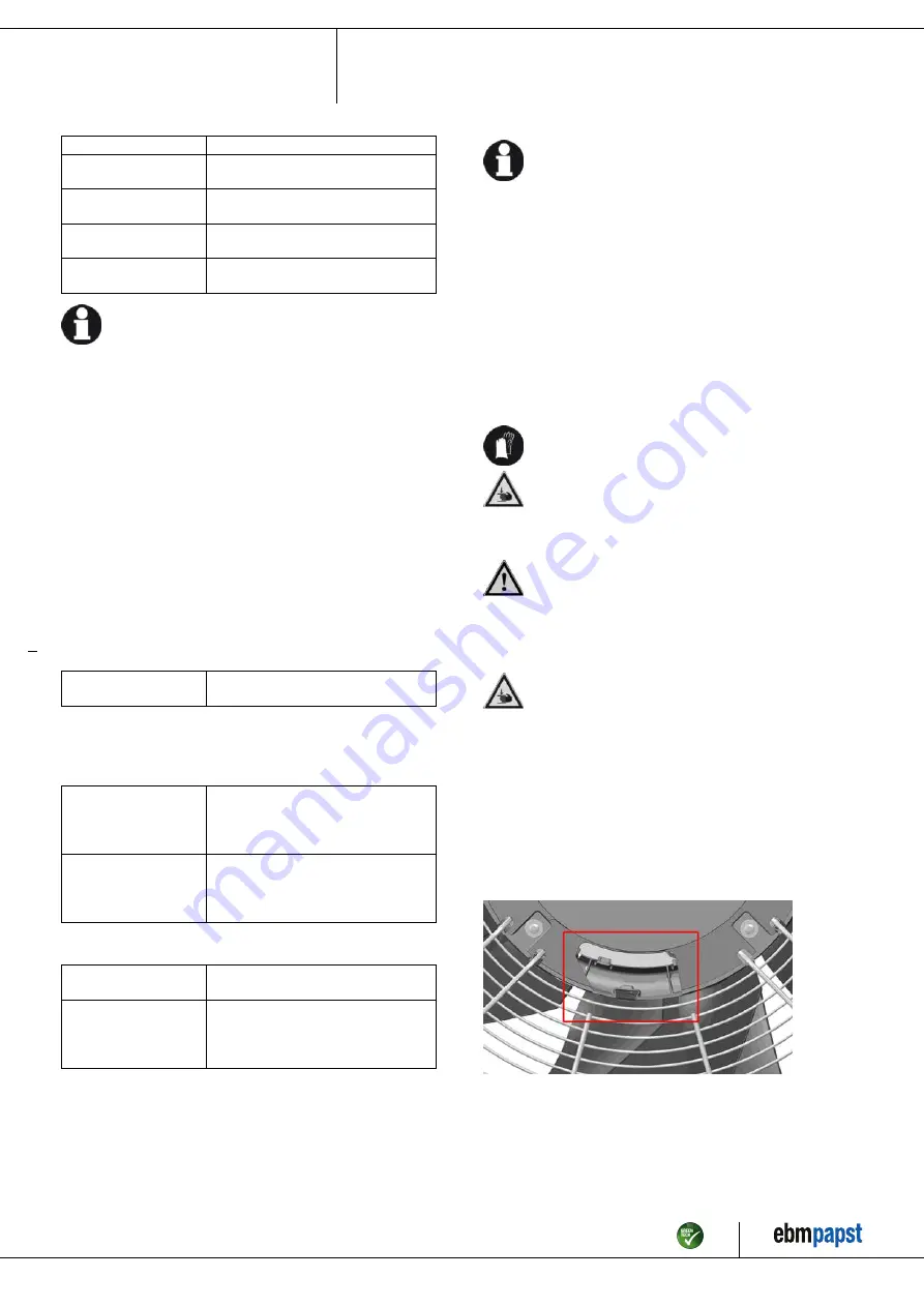
DANGER
There is a risk of serious injury occurring at the diffuser
cover recess!
Without connected lines or flexible tubes, the requirements of the
applicable standards (e.g. DIN EN ISO 13857 and UL1995)
with regard to safety distances to prevent hazard zones being
reached are not satisfied in the connection area.
→ Compliance with the required safety distances must be
ensured by laying the lines or flexible tubes over the critical
areas. Alternatively, compliance with the necessary safety
distances can be ensured by providing additional covering
(e.g. replacement of the diffuser cover fitted with the diffuser
cover 60802-2-2960 with connected lines).
Fig. 1: Recess for conduit glands in cover of internal diffuser
Item no. 57187-5-9970 · ENU · Change 209539 · Approved 2021-02-01 · Page 6 / 16
ebm-papst Mulfingen GmbH & Co. KG · Bachmühle 2 · D-74673 Mulfingen · Phone +49 (0) 7938 81-0 · Fax +49 (0) 7938 81-110 · info1@de.ebmpapst.com · www.ebmpapst.com


