background image

Operating instructions

W3G910-LU25-D1

Translation of the original operating instructions

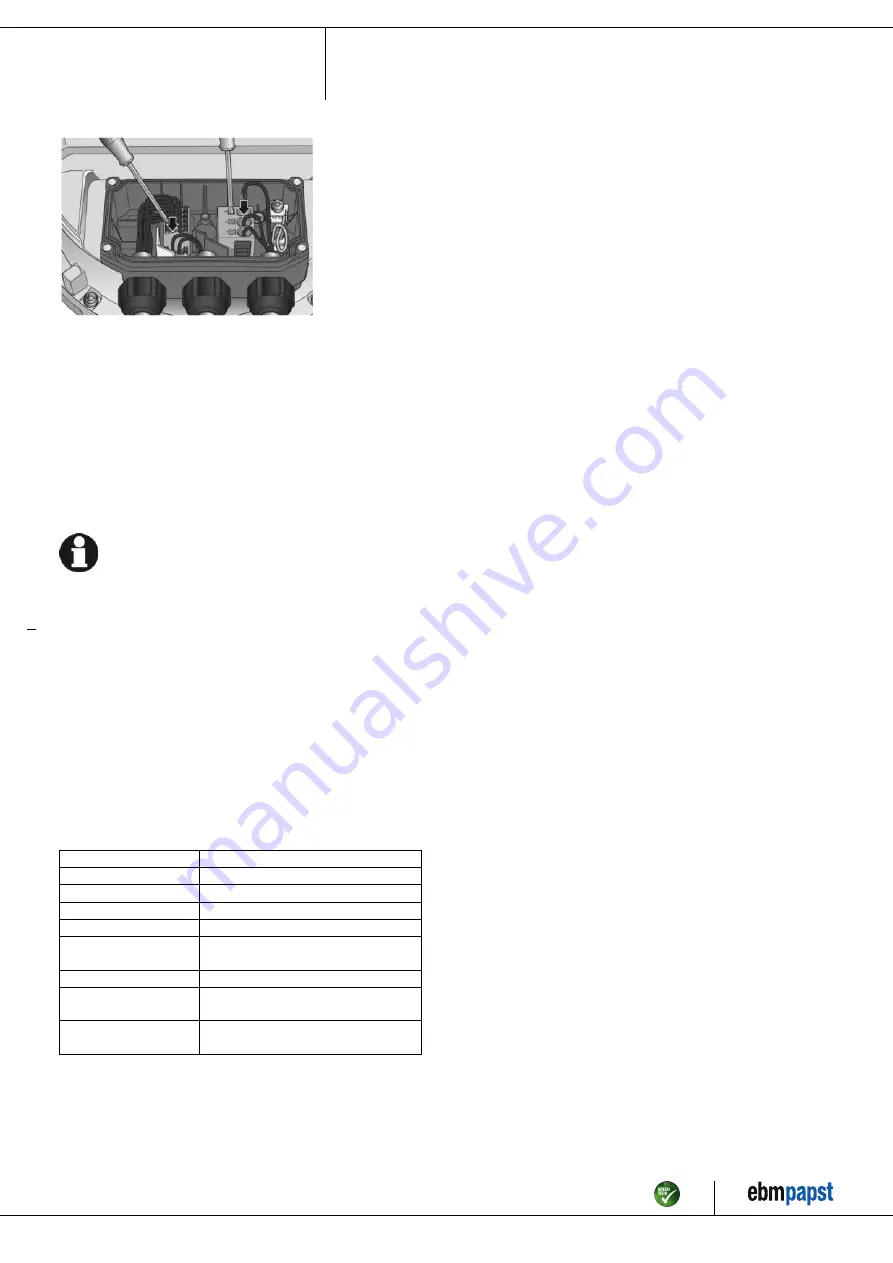
Fig. 4: Connection of cables at terminals

;

There must not be any tensile stress between the terminal and the
cable gland. The cable must be provided with strain relief.

;

The cable glands must be tight.

;

Fit the terminal box cover, making sure that the sealing surfaces are
clean.

;

Screw in the four screws (for tightening torque, see Chapter 3.1
Product drawing).

4.3.3 Cable routing

Water must be prevented from reaching the cable gland along the cable.

NOTE
Damage caused by moisture penetration.

Moisture can penetrate into the terminal box if water is
constantly present at the cable glands.
→ To prevent the constant accumulation of water at the cable

glands, the cable should be routed in a U-shaped loop
wherever possible.

→ If this is not possible, a drip edge can be produced by

fitting a cable tie directly in front of the cable gland for example.

Fans installed lying flat

Make sure the cable is routed in a U-shaped loop.

Fans installed upright

When routing the cable, make sure that the cable glands are located at
the bottom. The cables must always be routed downward.

4.4 Factory settings

Factory settings made for the device by ebm-papst.

Mode parameter set 1

PWM control

Mode parameter set 2

PWM control

Fan/device address

01

Max. PWM / %

100

Min. PWM / %

5

Save set value to
EEPROM

Yes

Set value requirement

Analog (linear)

Direction of action
parameter set 1

Positive (heating)

Direction of action
parameter set 2

Positive (heating)

Item no. 57187-5-9970 · ENU · Change 209539 · Approved 2021-02-01 · Page 9 / 16

ebm-papst Mulfingen GmbH & Co. KG · Bachmühle 2 · D-74673 Mulfingen · Phone +49 (0) 7938 81-0 · Fax +49 (0) 7938 81-110 · info1@de.ebmpapst.com · www.ebmpapst.com

Summary of Contents for W3G910-LU25-D1

Page 1: ...o carry out a test run and to perform work on the electrical installation 1 3 Basic safety rules 1 1 3 Basic safety rules The safety hazards associated with the device must be assessed again following...

Page 2: ...g in conjunction with open and closed loop control devices If impermissible radiation levels occur following installation appropriate shielding measures have to be taken by the user NOTE Electrical or...

Page 3: ...stationary systems Performing all maintenance work Conveying air at an ambient air pressure between 800 mbar and 1050 mbar Using the device within the permitted ambient temperature range see Chapter...

Page 4: ...V 2 Cable diameter min 6 mm max 12 mm tightening torque 4 0 6 Nm 3 Tightening torque 3 5 0 5 Nm 4 Tightening torque 3 0 3 Nm 5 Mounting holes for FlowGrid Item no 57187 5 9970 ENU Change 209539 Appro...

Page 5: ...s 100 000 Pa Data obtained at optimum efficiency level The ErP data is determined using a motor impeller combination in a standardized measurement setup 3 4 Technical description Weight 53 kg Size 910...

Page 6: ...d equipment with a total rated power greater than 1 kW If several devices are connected in parallel on the supply side so that the line current of the arrangement is in the range 16 75 A this arrangem...

Page 7: ...g on the fan secure the system machine in which the fan is installed so as to prevent it from being switched back on NOTE Device malfunctions possible Route the device s control lines separately from...

Page 8: ...t be taken to avoid damaging the paintwork of the terminal box if the cable glands are replaced This could lead to corrosion and leakage Only strip the cable as far as necessary ensuring that the cabl...

Page 9: ...routed in a U shaped loop wherever possible If this is not possible a drip edge can be produced by fitting a cable tie directly in front of the cable gland for example Fans installed lying flat Make...

Page 10: ...eristic curve P1 IN SELV CON2 IO3 Function parameterizable see Optional interface functions table Factory setting Analog output 0 10 V max 5 mA function Fan modulation level Characteristic curve param...

Page 11: ...159 0 Ain2 0 10V PWM analog input D159 2 Ri 100K characteristic curve parameterizable f PWM 1k 10KHz SELV Ain2 4 20mA analog input Ri 125R characteristic curve parameterizable SELV D159 3 Din3 active...

Page 12: ...operating instructions 4 7 Equivalent circuit diagrams Item no 57187 5 9970 ENU Change 209539 Approved 2021 02 01 Page 12 16 ebm papst Mulfingen GmbH Co KG Bachm hle 2 D 74673 Mulfingen Phone 49 0 793...

Page 13: ...supply Switching off the device for maintenance Switch off the device via the control input Do not switch the motor e g in cyclic operation on and off via power supply Disconnect the device from the p...

Page 14: ...us LED orange Message at status relay 1 Current limitation in action 2 Line impedance too high DC link voltage unstable 3 Power limiter in action 4 Output stage temperature high 5 Motor temperature hi...

Page 15: ...ls to the actual level of dust exposure 6 3 Safety inspection NOTE High voltage test The integrated EMC filter has Y capacitors The tripping current is exceeded when AC testing voltage is applied Test...

Page 16: ...num Non ferrous metal e g motor windings Plastics particularly with brominated flame retardants in accordance with marking Insulating materials Cables and wires Electronic scrap e g circuit boards Onl...

Reviews: