background image

Operating instructions

W3G910-LV12-D1

Translation of the original operating instructions

4.2.3 Reactive currents

Because of the EMC filter integrated for compliance with EMC
limits (interference emission and immunity to interference),
reactive currents can be measured in the supply line even
when the motor is at a standstill and the line voltage is switched
on.

The values are typically in the range < 250 mA

At the same time, the effective power in this operating state
(operational readiness) is typically < 5 W.

4.2.4 Residual current circuit breaker (RCCB)

If the use of a residual current device (RCD) is required in your
installation, only AC/DC-sensitive residual current devices
(type B or B+) are permissible. As with variable frequency
drives, residual current devices cannot provide personal safety
while operating the device. When the device power supply is
switched on, pulsed charging currents from the capacitors in the
integrated EMC filter can lead to the instant tripping of residual
current devices. We recommend the use of residual current
circuit breakers (RCCB) with a trip threshold of 300 mA and
delayed tripping (super-resistant, characteristic K).

4.2.5 Leakage current

For asymmetrical power systems or if a phase fails, the
leakage current can increase to a multiple of the nominal value.

4.2.6 Locked-rotor protection

Due to the locked-rotor protection, the starting current (LRA) is
equal to or less than the nominal current (FLA).

4.3 Connection in terminal box

4.3.1 Preparing cables for connection

NOTE
Care must be taken to avoid damaging the paintwork of
the terminal box if the cable glands are replaced.

This could lead to corrosion and leakage!

Only strip the cable as far as necessary, ensuring that the cable gland is
sealed and there is no strain on the connections. For tightening torques,
see Chapter 3.1 Product drawing.

NOTE
Tightness and strain relief are dependent on the cable
used.

→ This must be checked by the user.

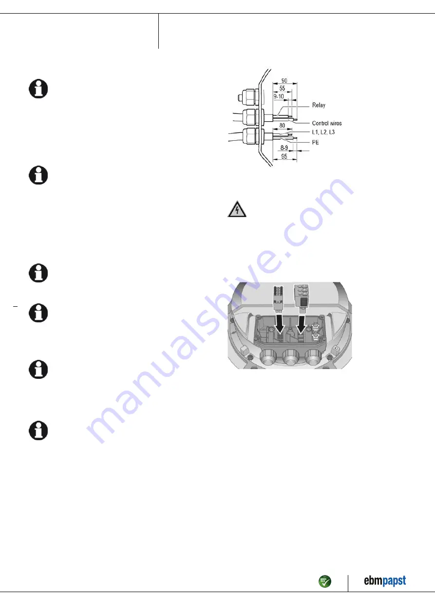
Fig. 2: Recommended stripped lengths in mm (inside terminal box)

4.3.2 Connect cables to terminals

WARNING
Live terminals and connections even with device
switched off

Electric shock
→ Wait five minutes after disconnecting the voltage at all poles

before opening the device.

;

Open the terminal box.

;

Remove the cap from the cable gland.

;

Only remove caps where cables are fed in.

Fig. 3: Fit the connectors in the terminal box

;

Fit the cable glands with the seals provided in the terminal box.

;

Route the cable(s) (not included in the scope of delivery) into the
terminal box.

;

Ensure separate routing of the supply cable(s) and the cables for
status contact and control interface. Depending on the requirements for
the end device, the physical separation of these cables in the terminal
box may be mandatory. Use the partitions inside the terminal box as
an aid to routing for this purpose.

;

First connect the protective earth "PE".

;

Connect the cables to the corresponding terminals. Use a
screwdriver to do so. When connecting, make sure the wires do not
splay out. Insert the strands until they meet with resistance.

Item no. 56413-5-9970 · ENU · Change 209539 · Approved 2021-02-01 · Page 8 / 16

ebm-papst Mulfingen GmbH & Co. KG · Bachmühle 2 · D-74673 Mulfingen · Phone +49 (0) 7938 81-0 · Fax +49 (0) 7938 81-110 · info1@de.ebmpapst.com · www.ebmpapst.com

Summary of Contents for W3G910-LV12-D1

Page 1: ...o carry out a test run and to perform work on the electrical installation 1 3 Basic safety rules 1 1 3 Basic safety rules The safety hazards associated with the device must be assessed again following...

Page 2: ...g in conjunction with open and closed loop control devices If impermissible radiation levels occur following installation appropriate shielding measures have to be taken by the user NOTE Electrical or...

Page 3: ...stationary systems Performing all maintenance work Conveying air at an ambient air pressure between 800 mbar and 1050 mbar Using the device within the permitted ambient temperature range see Chapter...

Page 4: ...V 2 Cable diameter min 6 mm max 12 mm tightening torque 4 0 6 Nm 3 Tightening torque 3 5 0 5 Nm 4 Tightening torque 3 0 3 Nm 5 Mounting holes for FlowGrid Item no 56413 5 9970 ENU Change 209539 Appro...

Page 5: ...fs 100 000 Pa Data obtained at optimum efficiency level The ErP data is determined using a motor impeller combination in a standardized measurement setup 3 4 Technical description Weight 58 5 kg Size...

Page 6: ...d equipment with a total rated power greater than 1 kW If several devices are connected in parallel on the supply side so that the line current of the arrangement is in the range 16 75 A this arrangem...

Page 7: ...g on the fan secure the system machine in which the fan is installed so as to prevent it from being switched back on NOTE Device malfunctions possible Route the device s control lines separately from...

Page 8: ...t be taken to avoid damaging the paintwork of the terminal box if the cable glands are replaced This could lead to corrosion and leakage Only strip the cable as far as necessary ensuring that the cabl...

Page 9: ...routed in a U shaped loop wherever possible If this is not possible a drip edge can be produced by fitting a cable tie directly in front of the cable gland for example Fans installed lying flat Make...

Page 10: ...eristic curve P1 IN SELV CON2 IO3 Function parameterizable see Optional interface functions table Factory setting Analog output 0 10 V max 5 mA function Fan modulation level Characteristic curve param...

Page 11: ...159 0 Ain2 0 10V PWM analog input D159 2 Ri 100K characteristic curve parameterizable f PWM 1k 10KHz SELV Ain2 4 20mA analog input Ri 125R characteristic curve parameterizable SELV D159 3 Din3 active...

Page 12: ...operating instructions 4 7 Equivalent circuit diagrams Item no 56413 5 9970 ENU Change 209539 Approved 2021 02 01 Page 12 16 ebm papst Mulfingen GmbH Co KG Bachm hle 2 D 74673 Mulfingen Phone 49 0 793...

Page 13: ...supply Switching off the device for maintenance Switch off the device via the control input Do not switch the motor e g in cyclic operation on and off via power supply Disconnect the device from the p...

Page 14: ...us LED orange Message at status relay 1 Current limitation in action 2 Line impedance too high DC link voltage unstable 3 Power limiter in action 4 Output stage temperature high 5 Motor temperature hi...

Page 15: ...ls to the actual level of dust exposure 6 3 Safety inspection NOTE High voltage test The integrated EMC filter has Y capacitors The tripping current is exceeded when AC testing voltage is applied Test...

Page 16: ...num Non ferrous metal e g motor windings Plastics particularly with brominated flame retardants in accordance with marking Insulating materials Cables and wires Electronic scrap e g circuit boards Onl...

Reviews: