


Operating instructions
W4E350-SN02-35
Translation of the original operating instructions
3. TECHNICAL DATA
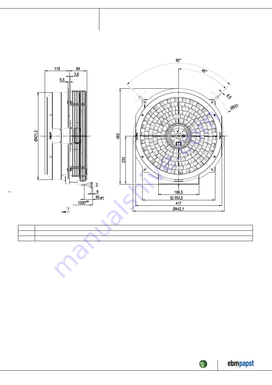
3.1 Product drawing
All dimensions in mm.
1
Airflow direction "V"
2
Cable silicone 4G 0.5 mm²
4x splice
Item no. 16554-5-9970 · ENU · Change 228768 · Approved 2021-02-17 · Page 4 / 11
ebm-papst Mulfingen GmbH & Co. KG · Bachmühle 2 · D-74673 Mulfingen · Phone +49 (0) 7938 81-0 · Fax +49 (0) 7938 81-110 · info1@de.ebmpapst.com · www.ebmpapst.com


