


Operating instructions
W4E450-CU03-02
Translation of the original operating instructions
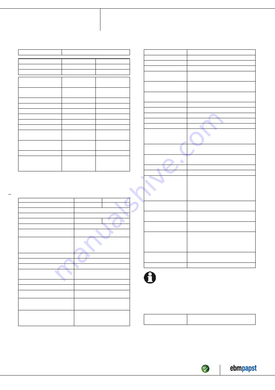
3.2 Nominal data
Motor
M4E094-EA
Phase
1~
1~
Nominal voltage / VAC
230
230
Frequency / Hz
50
60
Method of obtaining
data
ml
ml
Valid for approval/
standard
CE
CE
Speed (rpm) / min
-1
1300
1490
Power consumption / W
350
425
Current draw / A
1.55
1.87
Capacitor / µF
8
8
Capacitor voltage / VDB
450
450
Max. back pressure / Pa
120
50
Min. ambient
temperature / °C
-40
-40
Max. ambient
temperature / °C
55
45
Starting current / A
6.0
5.5
Max. safe operating
speed (rpm) /
min
-1
1950
@ 55 °C
1950
@ 55 °C
ml = Max. load · me = Max. efficiency · fa = Free air
cs = Customer specification · ce = Customer equipment
Subject to change
3.3 Data according to ErP Directive
Actual
Req. 2015
01 Overall efficiency η
es
/ %
32.9
30.6
02 Measurement category
A
03 Efficiency category
Static
04 Efficiency grade N
42.3
40
05 Variable speed drive
No
06 Year of manufacture
The year of manufacture is specified on the
product's rating label.
07 Manufacturer
ebm-papst Mulfingen GmbH & Co. KG
Amtsgericht (court of registration) Stuttgart
· HRA 590344
D-74673 Mulfingen
08 Type
W4E450-CU03-02
09 Power consumption P
e
/ kW
0.33
09 Air flow q
v
/ m³/h
3920
09 Pressure increase total p
sf
/
Pa
100
10 Speed (rpm) n / min
-1
1325
11 Specific ratio
*
1.00
12 Recycling/disposal
Information on recycling and disposal is
provided in the operating instructions.
13 Maintenance
Information on installation, operation and
maintenance is provided in the operating
instructions.
14 Additional components
Components used to calculate the energy
efficiency that are not apparent from the
measurement category are detailed in the
CE declaration.
*
Specific ratio = 1 + p
fs
/ 100 000 Pa
Data obtained at optimum efficiency level. The ErP data is determined using a motor-impeller
combination in a standardized measurement setup.
3.4 Technical description
Weight
9.5 kg
Fan size
450 mm
Rotor surface
Painted black
Terminal box material
ABS plastic
Blade material
Press-fitted sheet steel blank, sprayed
with PP plastic
Fan housing material
Sheet steel, galvanized and coated with
black plastic (RAL 9005)
Guard grille material
Steel, coated with black plastic (RAL
9005)
Number of blades
5
Airflow direction
"A"
Direction of rotation
Clockwise, viewed toward rotor
Degree of protection
IP54
Insulation class
"F"
Moisture (F) /
Environmental (H)
protection class
F4-1
Installation position
Shaft horizontal or rotor on bottom; rotor
on top on request
Condensation
drainage holes
On rotor side
Mode
S1
Motor bearing
Ball bearing
Touch current
according to IEC
60990 (measuring
circuit Fig. 4, TN
system)
<= 3.5 mA
Electrical hookup
Via terminal box, capacitor integrated and
connected
Motor protection
Thermal overload protector (TOP)
internally connected
Protection class
I (with customer connection of protective
earth)
Motor capacitor
according to EN 60252-
1 in safety protection
class
P0/S0
Conformity with
standards
EN 60034-1 (2010); CE
Approval
CCC; EAC
With regard to cyclic speed loads, note that the rotating parts of
the device are designed for a maximum of one million load
cycles. If you have special questions, consult ebm-papst for
support.
3.5 Mounting data
;
Secure the screws against unintentional loosening (e.g. use self-
locking screws).
Strength class of
screws
8.8
Any further mounting data required can be taken from the product drawing.
Item no. 14753-5-9970 · ENU · Change 89187 · Approved 2016-04-15 · Page 5 / 10
ebm-papst Mulfingen GmbH & Co. KG · Bachmühle 2 · D-74673 Mulfingen · Phone +49 (0) 7938 81-0 · Fax +49 (0) 7938 81-110 · info1@de.ebmpapst.com · www.ebmpapst.com


