


Operating instructions
W4E450-CU03-02
Translation of the original operating instructions
4.2.4 Variable frequency drive
Please use a variable frequency drive only after consultation with ebm-
papst.
When a variable frequency drive is used for speed adjustment, the
maximum safe operating speed (see 3.2 Nominal data) may not be
exceeded.
For operation with variable frequency drives, install sinusoidal
filters that work on all poles (phase-phase and phase-ground)
between the drive and the motor.
During operation with variable frequency drives, an all-pole
sine filter protects the motor against high-voltage transients that
can destroy the coil insulation system, and against harmful
bearing currents.
Heating of the motor due to use of a variable frequency drive must be
checked in the application by the customer.
4.3 Connection in terminal box
4.3.1 Preparing cables for connection
Only strip the cable as far as necessary, ensuring that the cable gland is
sealed and there is no strain on the connections. For tightening torques,
see Chapter 3.1 Product drawing.
NOTE
Tightness and strain relief are dependent on the cable
used.
→ This must be checked by the user.
4.3.2 Connecting wires to terminals
;
Remove the cap from the cable gland.
Only remove caps where cables are fed in.
;
Route the wire(s) (not included in scope of delivery) into the terminal
box.
;
First connect the "PE" (protective earth).
;
Connect the wires to the corresponding terminals.
Use a screwdriver to do so.
When connecting, ensure that no wire ends fan out.
;
Seal the terminal box.
4.3.3 Cable routing
Water must be prevented from reaching the cable gland along the cable.
Fans installed lying flat
Make sure the cable is routed in a U-shaped loop.
Fig. 2: Fan installed lying flat, cable routed in a U-shaped loop.
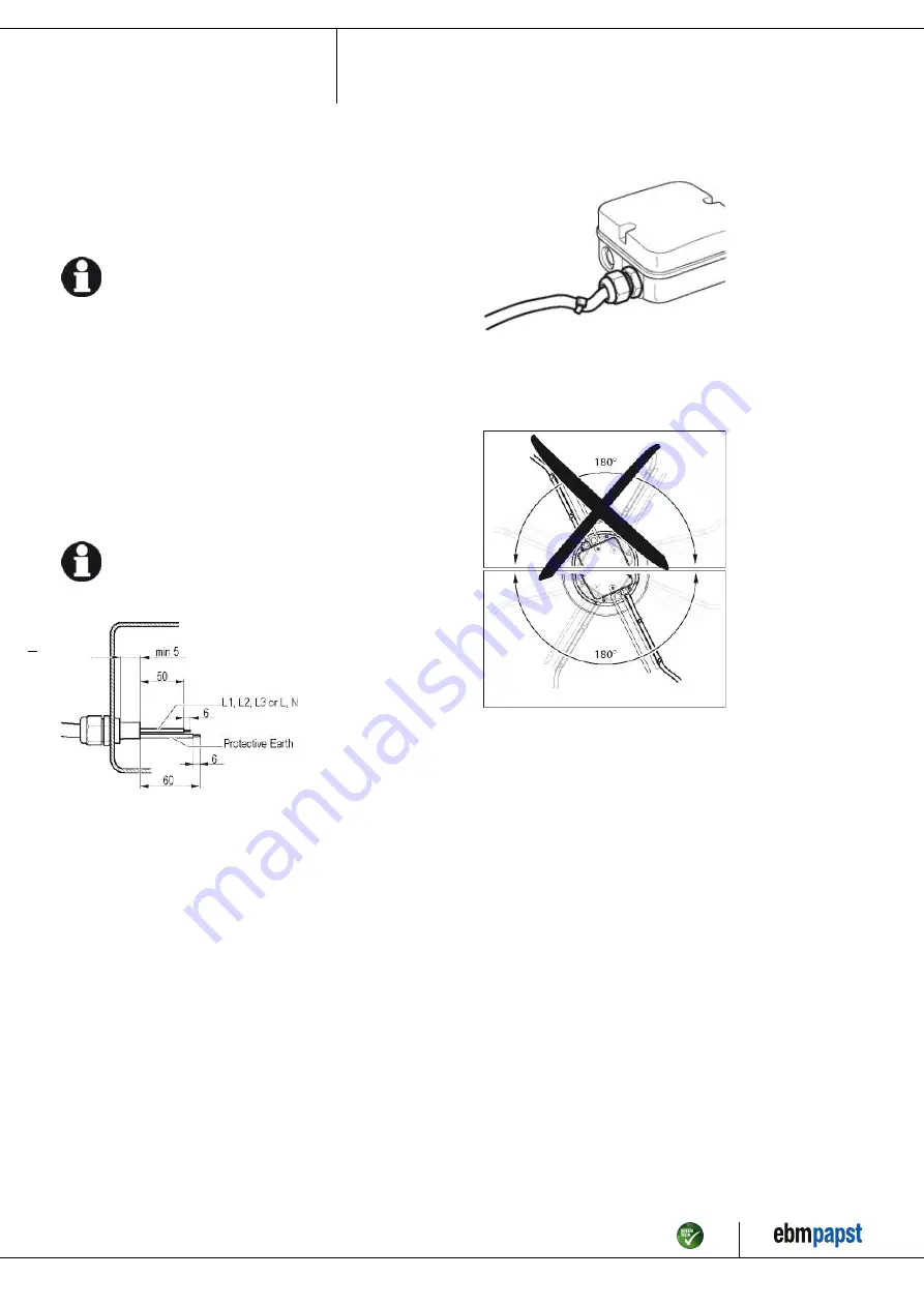
Fans installed upright
When routing the cable, make sure that the cable glands are located at
the bottom. The cables must always be routed downward.
Fig. 3: Cable routing for fans installed upright.
Item no. 14753-5-9970 · ENU · Change 89187 · Approved 2016-04-15 · Page 7 / 10
ebm-papst Mulfingen GmbH & Co. KG · Bachmühle 2 · D-74673 Mulfingen · Phone +49 (0) 7938 81-0 · Fax +49 (0) 7938 81-110 · info1@de.ebmpapst.com · www.ebmpapst.com


