


Operating instructions
W4E450-CU03-02
Translation of the original operating instructions
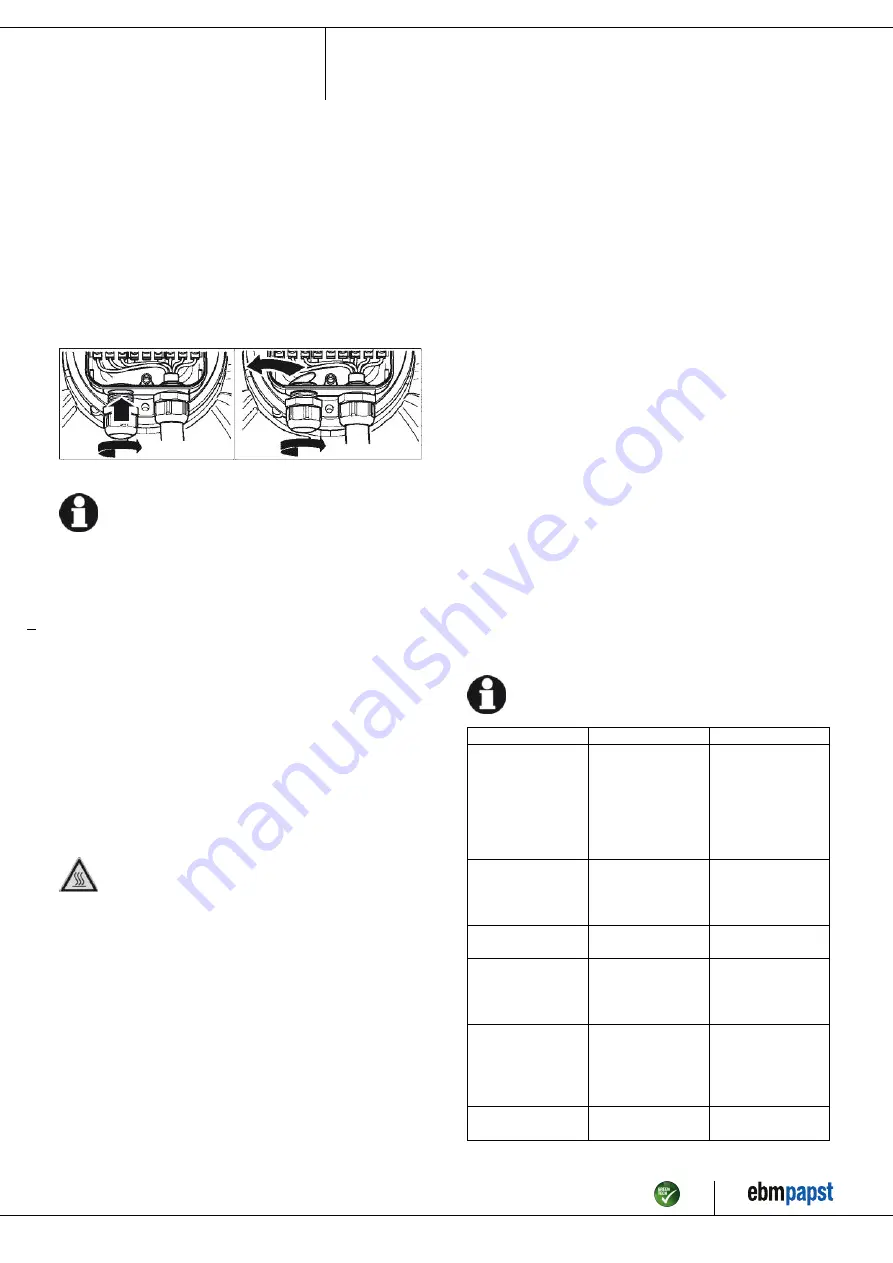
4.5 Opening additional cable glands
A second cable gland opening can be made in the terminal box.
WARNING
In the event of a fault, the cable gland is energized
Electric shock
→ Do not use metal cable glands with plastic terminal boxes.
;
Screw the cable gland into the precut thread using a wrench. When
doing so, take note of the tightening torques; see Chapter 3.1 Product
drawing.
;
Remove the plastic tab that fell off inside the terminal box when it was
penetrated.
Fig. 4: Cable gland opening
NOTE
Tightness and strain relief are dependent on the cable
used.
→ This must be checked by the user.
4.6 Checking connections
;
Ensure isolation from supply (all phases).
;
Make sure a restart is impossible
;
Check the cables for proper fit.
;
Screw the terminal box cover back on again. Terminal box tightening
torque, see Chapter 3.1 Product drawing.
;
Make sure the terminal box is completely closed and sealed and that
all screws and cable glands have been properly tightened.
4.7 Switching on the device
The device may only be switched on if it has been installed properly and
in accordance with its intended use, including the required safety
mechanisms and professional electrical hookup. This also applies for
devices which have already been equipped with plugs and terminals or
similar connectors by the customer.
WARNING
Hot motor housing
Risk of fire
→ Ensure that no combustible or flammable materials are
located close to the fan.
;
Before switching on, check the device for visible external damage
and make sure the protective devices are functional.
;
Check the fan's air flow paths for foreign matter and remove any
foreign matter found.
;
Apply the nominal supply voltage.
4.8 Switching off the device
;
Disconnect the device from the power supply at the supply line's
main switch.
;
When disconnecting, be sure to disconnect the ground connection last.
5. MAINTENANCE, MALFUNCTIONS, POSSIBLE
CAUSES AND REMEDIES
Do not perform any repairs on your device. Send the device to ebm-
papst for repair or replacement.
WARNING
Live terminals and connections even with device
switched off
Electric shock
→ Wait five minutes after disconnecting the voltage at all poles
before opening the device.
CAUTION
Electric charge on capacitor after device is switched off
Electric shock, risk of injury
→ Discharge the capacitors before working on the device.
CAUTION
The motor restarts automatically when operating voltage
is applied, e.g. after a power failure.
Risk of injury
→ Keep out of the device's danger zone.
→ When working on the device, switch off the line voltage
and ensure that it cannot be switched back on.
→ Wait until the device comes to a stop.
If the device is out of use for some time, e.g. when in storage,
we recommend switching it on for at least two hours to allow
any condensation to evaporate and to move the bearings.
Malfunction/fault
Possible cause
Possible remedy
Impeller not
running smoothly
Imbalance in rotating
parts
Clean the device;
replace it if imbalance
persists after cleaning.
Make sure no
weight clips are
removed during
cleaning.
Motor not turning
Mechanical blockage
Switch off, isolate
from supply and
remove mechanical
blockage.
Line voltage faulty
Check line voltage,
restore power supply.
Faulty connection
Isolate from supply,
correct connection;
see connection
diagram.
Thermal overload
protector activated
Allow motor to cool
off, locate and rectify
cause of error,
release restart lockout
if necessary
Impermissible point of
operation
Check point of
operation
Item no. 14753-5-9970 · ENU · Change 89187 · Approved 2016-04-15 · Page 9 / 10
ebm-papst Mulfingen GmbH & Co. KG · Bachmühle 2 · D-74673 Mulfingen · Phone +49 (0) 7938 81-0 · Fax +49 (0) 7938 81-110 · info1@de.ebmpapst.com · www.ebmpapst.com


