background image


5. 

5. 

Touch Panel Settings (TM Series) 

Note: 

If the touchscreen monitor you used is not WTM or TM series, please refers to 

the user manual of it for touch screen driver operation.


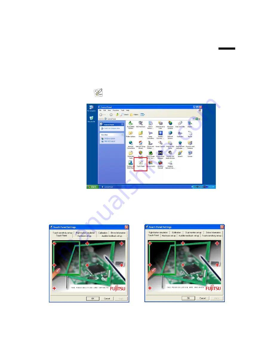
To launch Touch Panel Settings, click 

Start

, click 

Control Panel

, and then 

double-click 

 icon. 


Note:

 The contents of this chapter are extracted from 

Fujitsu Touch Panel (Serial) Device 

driver setting manual V1.0L24. 

“Fujitsu” is the registered trademark of 

FUJITSU LIMITED


5.1. Start screen of Touch Panel Settings 


Single Monitor


Dual Monitor 

(

Plug and Play Device

)


Non-Plug and Play Device


Chapter 5


26 

Summary of Contents for BPC65-B-A16G

Page 1: ...User s Manual BPC65 B A16G...

Page 2: ...diate radio frequency energy and if not installed and used in accordance with the instructions may cause harmful interference to radio communications However there is no guarantee that interference wi...

Page 3: ...eturn and recycling of used appliances as applicable throughout the European Union This label is applied to various products to indicate that the product is not to be thrown away but rather reclaimed...

Page 4: ...stallation 6 3 2 Chipset Software Installation 6 3 3 VGA Driver Installation 8 3 4 Touch Screen Driver and Software Utility installation 11 3 4 1 WTM series 11 3 4 2 TM 550 Touch Monitor 14 3 5 LAN Dr...

Page 5: ...Double click setting 30 5 5 Right button simulation 30 Right click simulation 30 Display the icon in the task bar tray 31 Display the icon in the Window 31 5 6 Calibration 32 Touch Panel controller fe...

Page 6: ...7 2 The Wall Mount Kit 42 7 3 Build in Dimension 43 v Contents...

Page 7: ...1 1 Hardware Setup 1 1 Unpacking the Box The Device X 1 Power Adaptor X 1 Power Cord X 1 Driver and Utility CD X 1 Chapter 1 1...

Page 8: ...2 2 Quick Tour 2 1 Front View 2 2 Rear View The Power indicator will glow green when power is on The HDD indicator will blink green when the HDD is accessed Chapter 2 2...

Page 9: ...ion 2 3 Peripherals Installation Power Adapter Connect the output jack of the adapter to the DC 12V jack on the back panel of the device USB Mouse USB Keyboard and USB ODD Connect your USB Mouse USB K...

Page 10: ...r LCD panel 2 Connect one end of the VGA cable to the VGA female port on the back panel of the device another end to the VGA port of your LCD panel LAN Cable Connect one end of RJ 45 LAN cable to the...

Page 11: ...Vertical Stand 2 4 Turn on the Device 1 Make sure all peripherals are connected properly 2 Press and hold the power switch until the power indicator on the front panel glow green Chapter 2 5...

Page 12: ...screen 2 Follow the on screen instructions For Model without CD ROM Onboard 1 Connect an external USB CDROM to the USB power and insert the driver CD and turn on the device The program autoruns and d...

Page 13: ...3 Click Next 4 Read the License Agreement carefully and click Yes 4 Click Next Chapter 3 7...

Page 14: ...6 Click Finish 3 3 VGA Driver Installation 1 On the main screen click BOXPC 65 Series 2 Click VGA Driver Chapter 3 8...

Page 15: ...3 Click VGA Driver for WIN2K XP 4 Click Next 5 Read the License Agreement carefully and click Yes Chapter 3 9...

Page 16: ...6 Click Next 7 Click Next 8 1 Select restart your computer right now or later and then lick Finish Chapter 3 10...

Page 17: ...M series please refers to the user manual of it for touch screen driver installation 3 4 1 WTM series The installation procedure shown below is based on Microsoft Windows XP 1 On the main screen click...

Page 18: ...nd then click Next Or you can click Next go to next screen directly 6 Click Browse to select the start menu folder and then click Next Or you can click Next go to next screen directly 6 This screen di...

Page 19: ...hange settings click Back to return to previous screens 7 During the installation the following screen will be displayed 8 The message below shows after the installation was successful Click OK to com...

Page 20: ...3 4 2 TM 550 Touch Monitor 1 Click TM70 WTM60 TM550 TM515 Series 2 Click Touch Driver 3 Click Touch Driver For TM550 TM515 Series Chapter 3 14...

Page 21: ...4 Click Next 5 Select an item according to your needs and then click Next Click the OK button on the pop up message 6 If you want to use Multi Monitor check the box and click Next Chapter 3 15...

Page 22: ...7 Click Next 8 Click Next 9 Click Next Chapter 3 16...

Page 23: ...9 The driver starts to install 10 Click OK 3 5 LAN Driver Installation 1 After clicking BOXPC 65 Series on the main screen click RTL8111C Lan Driver Chapter 3 17...

Page 24: ...2 1 On the welcome screen click Next 2 2 Click Install to begin the installation 3 Click Finish Chapter 3 18...

Page 25: ...ial port information of the system b Virtual Button Open the virtual button setting dialogue box c Feedback Sound Open the feedback sound setting dialogue box d Power Save Open the power down timer ad...

Page 26: ...ected option will be in black Virtual Button Option Under Virtual Button Option field there are four options Stream Mode Under this mode all mouse button simulation will be disabled Lift off Mode Unde...

Page 27: ...the Drag Drop Mode under Virtual Button Option field is select the drop down menu below the Enable On option will be enabled Automatic Mode Select this option the Right Button Function will switch to...

Page 28: ...e value is 0 5 and maximum value is 5 Click the drop down menu to select On or Off to enable or disable the beep sound effect for toggle on and toggle off 4 5 Feedback Sound Click Feedback Sound butto...

Page 29: ...mum value is 50 The selected option will be in black 4 6 Screen Calibration 1 Click the drop menu next to the Calibration button to select calibration mode 4 points mode 1 rectangular four point calib...

Page 30: ...low the instruction in green to touch the center of Cross Mark c When the instruction turns into yellow releasing the tapping from the screen d Follow the instruction in green to touch the center of C...

Page 31: ...Yes to restore the old calibration click No How to Use Event Selector 1 On the desktop of Windows click icon 2 icon change to 3 Now the tapping is simulating right mouse button clicking 4 After one t...

Page 32: ...h Touch Panel Settings click Start click Control Panel and then double click icon Note The contents of this chapter are extracted from Fujitsu Touch Panel Serial Device driver setting manual V1 0L24 F...

Page 33: ...of touch panel controller from 10ms to 155ms by 5ms step Mouse Cursor Setting Delete Cursor check box The display of the mouse cursor is deleted The special cursor of other application isn t deleted b...

Page 34: ...COM Input the COM port number that the device is connected I O Input the I O address that the device is connected IRQ Input the IRQ number that the device is connected Data interval time Using slider...

Page 35: ...ault setting Sound disabled Sound when pressed Beep Sound Frequency 1000Hz Beep time 50ms Set it as user default button Present sound settings are preserved as standard setting Contents preserved are...

Page 36: ...orizontal range recognized as double clicking is set 2 32 pixel Height The vertical range recognized as double clicking is set 2 32 pixel Speed The maximum time between clicks recognized as double cli...

Page 37: ...without cooperative key operation when checked Display the icon in the Window The icon of the mouse style see figures below is registered in the desktop and right click simulation works without coope...

Page 38: ...Calibration can t be carried out until OK and Apply button are pushed and a setup is renewed The calibration is done so that pressed position of touch panel device matches to the display position When...

Page 39: ...e calibration program Arrow keys Move the calibration point mark Enter Revise the calibration data and skip to test screen Test screen You can do free drawing in this screen so that the result of the...

Page 40: ...lose the key box window and screen changes to the style below Key input of this drawing test screen Home Back to calibration screen Tab On and off the cursor display on the screen Delete Clear the scr...

Page 41: ...e as actual monitor arrangement Monitor 1 Select the resolution of monitor1 Monitor 2 Select the resolution of monitor2 Use port Monitor 1 Click the drop down list to select the port of the touch pane...

Page 42: ...owings 6 1 Power Connector Pin Signal Name 1 NC 2 12V 3 GND 6 2 Serial Port 1 2 3 4 Pin Signal 1 DCD Data carrier detect 2 RXD Receive data 3 TXD Transmit data 4 DTR Data terminal ready 5 GND ground 6...

Page 43: ...of COM1 RI Default Pitch 2 54mm YIMTEX 3322 05SAGR 6T JP5 6 7 COM2 3 4 Signal Power Selection Jumper Setting Function 1 3 Short Pin 1 of COM2 3 4 12V 3 5 Short Pin 1 of COM2 3 4 5V 5 7 Short Pin 1 of...

Page 44: ...Chapter 6 38...

Page 45: ...0 GND 3 Blue 11 NC 4 NC 12 DDC2B data 5 GND 13 HSYNC 6 GND 14 VSYNC 7 GND 15 DDC2B clock 8 GND 6 4 LAN and USB 1 2 Pin Signal Pin Signal 1 MDI 0 U1 5V 2 MDI 0 U2 USB0 3 MDI 1 U3 USB0 4 MDI 1 U4 GND 5...

Page 46: ...6 5 USB 3 4 Pin Signal Name Pin Signal Name 1 5V 5 5V 2 USB1 6 USB0 3 USB1 7 USB0 4 GND 8 GND Chapter 6 40...

Page 47: ...7 7 Specification 7 1 The Device Chapter 7 41...

Page 48: ...7 2 The Wall Mount Kit Chapter 7 42...

Page 49: ...7 3 Build in Dimension For the best thermal efficiency and safety when installing or mounting the device in a cabinet or rack the minimum clearance distance show be kept as followed Chapter 7 43...

Page 50: ...ni PCI optional wireless LAN module Expansion Others Support VESA Mount Wall Mount External Adapter 60W 12VDC Input Power Supply FCC CE WEEE RoHS CCC Compliance Approx 1 43 Kg Weight 189 W x 179 Dx 52...

Reviews: