background image


Chapter 2


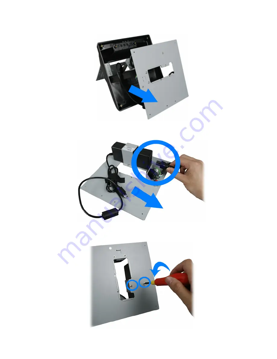
7.  Remove the base chassis. 


8.  Unplug the AC inlet as shown below. 


9.  Loosen and remove the two screws fixing the power adapter bracket by #1 

Phillips screwdriver. 


Summary of Contents for POS50A-5B-LX800

Page 1: ...5 5B B L LX X8 80 00 0 P PO OS S5 50 0A A 2 2B B L LX X8 80 00 0 P PO OS S5 50 0A A 8 8B B L LX X8 80 00 0 P PP PC C5 50 0A A 5 5B B L LX X8 80 00 0 P PP PC C5 50 0A A 2 2B B L LX X8 80 00 0 P PP PC...

Page 2: ...of this manual may be reproduced by any mechanical electronic or other means in any form without prior written permission of the manufacturer All trademarks are property of their respective owners Li...

Page 3: ...Only 2 POS50A Series Only The Main Unit t 7 The Main Uni 3 1 Opening the Device 7 3 2 HDD Disassemble 8 3 3 EMI AD Cover Disassemble 8 3 4 LED Indicator Disassemble 10 3 5 Speaker Assembly Disassembl...

Page 4: ...ment carefully Failure to follow these instructions could damage your device and void the warranty 1 1 Tools Suggested All procedures in this document require the following tools 0 Phillips screwdrive...

Page 5: ...mble P PO OS S5 50 0A A S Se er ri ie es s O On nl ly y 1 Adjust the main unit to the position as shown below 2 Unplug the power adapter connecter 3 Loosen and remove the four screws fixing the base u...

Page 6: ...4 Remove the right hinge cover left hinge cover and support cover as shown below 5 Remove the base unit 6 Loosen the four screws to remove the four rubber pads by 1 Phillips screwdriver Chapter 2 3...

Page 7: ...Chapter 2 4 7 Remove the base chassis 8 Unplug the AC inlet as shown below 9 Loosen and remove the two screws fixing the power adapter bracket by 1 Phillips screwdriver...

Page 8: ...dapter and the power adapter bracket 11 Loosen and remove the two screws fixing the AC inlet bracket by 1 Phillips screwdriver 12 Loosen and remove the screw fixing the grounding wire by 1 Phillips sc...

Page 9: ...Chapter 2 6 13 Remove the AC inlet...

Page 10: ...3 Chapter 3 7 T Th he e M Ma ai in n U Un ni it t 3 1 Opening the Device 1 Loosen and remove the twelve screws fixing the back cover by 1 Phillips screwdriver 2 Remove the back cover...

Page 11: ...2 HDD Disassemble 1 Disconnect the IDE cable and loosen the four screws fixing the HDD as shown below 3 3 EMI AD Cover Disassemble 1 Loosen and remove the twelve screws fixing EMI AD cover by 1 Philli...

Page 12: ...2 Loosen and remove the four hexagonal bolts fixing COM ports by hexagon socket spanner 3 Open the EMI AD cover Chapter 3 9 4 Unplug the power switch to remove the EMI AD cover...

Page 13: ...Chapter 3 10 5 Unplug the IDE cable 3 4 LED Indicator Disassemble 1 Unplug the LED indicator connecter from the main board 2 Unplug the three green LED indicator from the LED bracket...

Page 14: ...3 5 Speaker Assembly Disassemble 1 Unplug the Speaker Assembly connecter from the main board 2 Remove the two screws fixing the speaker 3 Remove the two screws fixing the speaker Chapter 3 11...

Page 15: ...er 3 12 3 6 Inverter Disassemble 1 Unplug the inverter cable 2 Unplug the connecter as shown below 3 Unplug the connecter as shown below 4 Loosen and remove the two screws fixing the inverter by 1 Phi...

Page 16: ...tow ejectors on the slot by pushing them and remove the RAM from the slot 2 Remove the old RAM and install a new one 3 Align and insert the new RAM in the slot and push both ends of the RAM down until...

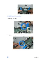
Page 17: ...Chapter 3 14 3 8 Main Board Disassemble 1 Unplug the LCD cable 2 Unplug the touch panel connecter as shown below...

Page 18: ...four screws fixing the main board by 1 Phillips screwdriver 4 Remove the LX 800 main board 3 9 LCD Panel Assembly Dissemble 1 Loosen the two screws fixing the LED lens by 1 Phillips screwdriver as sh...

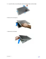
Page 19: ...Chapter 3 16 2 Loosen and remove the ten screws fixing the back cover by 1 Phillips screwdriver 3 Remove the LCD panel assembly as shown below 4 Loosen the four screws as shown below...

Page 20: ...5 Loosen the three screws fixing the touch panel other sides as shown below 6 Remove the touch panel 7 Remove the LCD panel Chapter 3 17...

Reviews: