background image

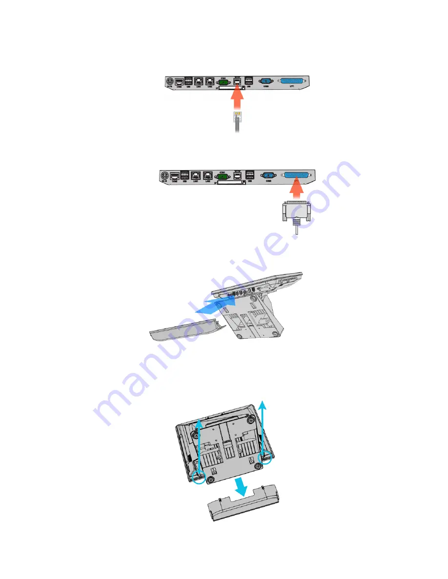
Cash Drawer 

Connect one end of RJ-11 cable to the 

Cash Drawer

 port on the back panel of the 

device, another end to your cash drawer. 


Printer 

Connect parallel cable of the printer to the LPT1 (parallel port ) on the back panel 
of the device. 


Install the IO panel cover onto the device. 


WiFi Module 

1. Remove the IO panel cover (if installed) form the device, remove the two 
screws, and then open the device. 


Chapter 1 

10

Summary of Contents for X-POS 850A

Page 1: ...User s Manual X POS 850A...

Page 2: ...and can radiate radio frequency energy and if not installed and used in accordance with the instructions may cause harmful interference to radio communications However there is no guarantee that inter...

Page 3: ...n and recycling of used appliances as applicable throughout the European Union This label is applied to various products to indicate that the product is not to be thrown away but rather reclaimed upon...

Page 4: ...able 9 Cash Drawer 10 Printer 10 WiFi Module 10 Customer Display 13 MSR 15 1 3 Adjust Angle 17 1 4 VESA Wall mount Kit Installation 17 1 5 Turn on the device 18 2 Basic Driver Installation 19 2 1 Befo...

Page 5: ...4 I O Definition 41 5 1 Power Connector 41 5 2 Serial Port 41 5 3 Cash Drawer 41 5 Specification 43 iv Contents...

Page 6: ...1 1 Hardware Setup 1 1 Quick Tour Front View and Side View LED Indicator The Power indicator will 1 glow green when the power is on 2 glow red when the HDD is accessed Chapter 1 5...

Page 7: ...Back Panel I O 1 2 Basic Peripherals Installation Remove the cable cover WARNING Before the cable cover is removed please make sure the power is off Chapter 1 6...

Page 8: ...s from peripherals to the I O of the POS device are recommended to be connected in the direction as shown below Power Adapter 1 Remove the two screens from the device as shown below 2 Remove the adapt...

Page 9: ...3 Feed the DC cable of the power adapter through the base as shown below 4 Feed the power cable through the base as shown below 5 Assembly all components as shown below Chapter 1 8...

Page 10: ...B Mouse USB Keyboard and USB ODD Connect your USB Mouse USB Keyboard and USB ODD to USB 1 2 or UBS 3 4 ports on the back panel of the device LAN Cable Connect one end of RJ 45 LAN cable to the LAN 1 o...

Page 11: ...her end to your cash drawer Printer Connect parallel cable of the printer to the LPT1 parallel port on the back panel of the device Install the IO panel cover onto the device WiFi Module 1 Remove the...

Page 12: ...2 Un tighten two screws 3 Open the back panel 4 Remove all 14 screws as shown 5 Remove the LCD and touch assembly Chapter 1 11...

Page 13: ...tenna and WiFi module cable as shown 8 Connect the another end of the WiFi module cable to the 4 pin USB header USB 8 on the main board For the location of the USB8 on the main board please refer to t...

Page 14: ...stallation 1 Remove the two screws fixing the customer display cover 2 Remover the VFD mounting hole cove from the device and pull out the connector from the device 3 Adjust the hinge of the VFD and t...

Page 15: ...w keys to select Super IO Configuration then type ENTER The screen below will appear Use the arrow keys to select Serial Port 6 RI 12V depending on what port the customer display is connected to Selec...

Page 16: ...agree with it MSR 1 Remove the two screws fixing the MSR cover Remove the MSR cover from the device 2 For MSR with fingerprint sensor or MSR with RFID sensor connect the two connectors of the MSR ass...

Page 17: ...to the device MSR with fingerprint sensor MSR with RFID sensor MSR MSR with iButton 3 Tighten the two M3 screws to fix the MSR assembly as shown below 4 Finished MSR with RFID sensor Chapter 1 16...

Page 18: ...t sensor MSR MSR withiButton 1 3 Adjust Angle 1 4 VESA Wall mount Kit Installation 1 Install the device bracket 2 Put the XPPC 850 onto the wall bracket which is preinstalled on the wall 3 Tighten the...

Page 19: ...1 5 Turn on the device 1 Make sure all peripherals are connected properly 2 Press and hold the power switch until the power indicator on the front panel glows green Chapter 1 18...

Page 20: ...he USB power and insert the driver CD and turn on the device The program autoruns and displays the DRIVER BANK screen 2 Follow the on screen instructions 2 2 Chipset Software Installation 1 On the mai...

Page 21: ...4 Read the License Agreement carefully and click Yes 4 Click Next 6 Click Finish Chapter 2 20...

Page 22: ...VGA Driver Installation 1 On the main screen click XPOS 850 XPPC850 Series 2 Click VGA Driver 3 Click VGA Driver for WIN2K XP 4 Click Next 5 Read the License Agreement carefully and click Yes Chapter...

Page 23: ...ext 7 Click Next 8 Select restart your computer right now or later and then lick Finish 2 4 Touch Screen Driver and Software Utility installation 1 On the main screen click XPOS 850 XPPC850 Series Cha...

Page 24: ...2 Click Touch Panel Driver 3 The procedure starts 4 Click Next 5 Check the Install PS 2 interface driver box and click Next Chapter 2 23...

Page 25: ...6 Select an item according to your needs and then click Next 7 Click OK 8 If you want to use Multi Monitor check the box and click Next 9 Click Next Chapter 2 24...

Page 26: ...10 Click Next 11 The driver starts to install 12 Click OK Chapter 2 25...

Page 27: ...2 5 LAN Driver Installation 1 On the main screen click XPOS 850 XPPC850 Series 2 Click VIA 6130 LAN Drive 3 The driver will be installed automatically 4 Click OK on the pop up message box Chapter 2 26...

Page 28: ...2 6 Audio Driver Installation 1 The driver is preparing to install 2 Click Next 3 Select I Agree and click Next 4 Check VIA HD Audio Codec Drive v7 300 30 090715 box and then click Next Chapter 2 27...

Page 29: ...5 Click Next 6 Click Next 7 Select restart your computer right now or later and then lick Finish Chapter 2 28...

Page 30: ...ouchKit Utility There are two alternatives to launch TouchKit Option 1 Under Microsoft Windows XP click start menu and select Programs under TouchKit menu click Configure Utility Option 2 Click icon o...

Page 31: ...ally USB TouchKit device supports plug and play the icon object for USB controller will be shown in the controller list window automatically when the USB controller is connected with the USB port of t...

Page 32: ...troller will be shown in the controller list window automatically when the USB controller is connected with the USB port of the device And the icon object for the USB controller will disappear automat...

Page 33: ...n Linearization Style TouchKit utility provides you with both 9 points and 25 points calibration for linearization You can select the suitable linearization type Double Click Time Double Click Time is...

Page 34: ...always generate mouse move event and is tracking the touch position until the touchscreen state switched to un touch state Click On Release With this Click On Release mode the driver emulates a mouse...

Page 35: ...ation for some advanced functions with this option button Press this button a pop up property sheet window will be popped up and shown as below 3 4 Tools There are function buttons and check boxes in...

Page 36: ...e buttons and follow the instruction on the screen to do the screen calibration Draw Test After clicking this button you can do the drawing test by drawing any path on the screen as shown below You ca...

Page 37: ...When this function is disabled the touchscreen will be mapped to the primary monitor automatically When this function is enabled user can double click on the monitor area in the monitor geometry wind...

Page 38: ...will be mapped to the full screen of the specified monitor Right screen The touchscreen will be mapped to the right half screen of the specified monitor Left screen The touchscreen will be mapped to...

Page 39: ...mapping area for application With this mode the driver does not correct the mapping area when the display resolution changed It needs to do configuration setting again whenever the display resolution...

Page 40: ...ill extend the vertical position of the left edge Right If you set the Edge to Smaller TouchKit will reduce the vertical position of the right edge If you set the Edge to Larger TouchKit will extend t...

Page 41: ...on to adjust the smaller or larger of edge If you click 10 button the top bottom left and right edges will extend 10 of orientation to touch screen and cursor will be moved 10 pixel of X and Y Axis to...

Page 42: ...Connector PIN Description PIN Description 1 19V 3 GROUND 2 19V 4 GROUND 5 2 Serial Port COM Port 1 2 3 PIN Description PIN Description 1 DCD 6 DSR 2 RXD 7 RTS 3 TXD 8 CTS 4 DTR 9 RI 5V 12V 5 GND 10 N...

Page 43: ...Cash Drawer Control Status Address Value Open 280H Bit 4 0 Close 280H Bit 4 1 Read Status 281H Bit 0 0 1 Chapter 5 42...

Page 44: ...5 5 Specification Chapter 5 43...

Page 45: ...232 422 485 DB 9 COM 2 RS232 RJ45 10 pins COM 3 RS232 DB 9 COM 4 RS232 Internal pin header COM 5 RS232 Internal 15 Pin header with PS 2 COM 6 RS232 Internal pin header for Customer Display Parallel 1...

Reviews: