background image


CPX230NWB ALARM CONTROL UNIT – USER MANUAL 


12 / 42 


EN 

4.


 WIRELESS KEYPAD KP2W 

The wireless keypad KP2W is intended as a secondary keypad. It allows only to: 


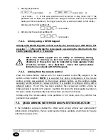
arm/disarm the system in a full and circuital mode 


activation of attack, fire and medical alarm analogically as for main keypad operation. 

Keep in mind, that the wireless keypad KP2W uses one-way transmission and cannot receive 
communication from the control panel. 

The keypad KP2W is equipped with keys marked with numbers 

to 

9

 and function keys 


and 


After pressing any key, the keypad is backlit. 

4.1.


TRANSMISSION 

The transmission is signaled by blinking of the blue transmission LED located in the lower 

right  corner  of  the  display.  This  means  that  the  information  is  send  to  the  alarm  control 
panel. 
The keypad transmits the entered characters as soon as any of the following conditions is 

met: 

a)


key 

 or 

 is pressed 

b)


8 keys are pressed 

c)


after 3 seconds of pressing the last key 

4.2.


LED SIGNALLING 

The keypad KP2W is equipped with two LEDs that inform about low battery and sending a 

radio transmission. 
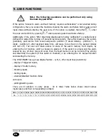
The low battery is signalled by showing a red battery symbol in the upper left corner of the 
display: 


After such icon appears, the battery should be replaced as soon as possible. 
 
Each  user-called  keypad  transmission  to  the  system  is  signalled  by  the  LED  in  the  lower 

right corner of the keypad display: 
 
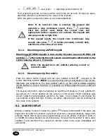
Displaying this symbol during operation means sending data to the alarm control panel and 

is a normal and desired device operation. 

Summary of Contents for CPX230NWB

Page 1: ...Version of the manual v1 3 Date of issue 26 07 2018 EN ALARM CONTROL PANEL CPX230NWB User manual Firmware version 2 10 0 GPRS transmitter configurator version 1 4 85 3 OSM server version 1 3 71 036...

Page 2: ...not be deemed to be providing any warranties either express or implicit including but not limited to any implied warranties of merchantability or fitness for a particular purpose unless it is required...

Page 3: ...KP2W KEYPAD 18 7 4 3 ARMING FROM THE REMOTE 18 7 5 QUICK ARMING WITH MODE AND PARTITION SELECTION 18 7 5 1 ARMING USING A KP32 KEYPAD 19 7 5 2 ARMING USING A KP2W KEYPAD 20 7 5 3 QUICK SWITCHING OF A...

Page 4: ...OL UNIT USER MANUAL 4 42 EN 9 10 PROGRAMMING TIME 30 9 11 PROGRAMMING DATE 31 9 12 TESTING THE ZONES 31 9 13 TESTING THE OUTPUTS 31 9 14 DURESS CODE 32 9 15 EMERGENCY BUTTONS 32 9 16 TEXT MESSAGES 32...

Page 5: ...ter intended for small and medium sized facilities The control panel is equipped with 3 outputs and 7 wired for TEOL configuration up to 14 and up to 32 wireless zones with the possibility to be divid...

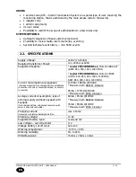
Page 6: ...50mA 1 keypad output max current 100mA PARTITIONS 2 partitions with the possibility to assign any number of zones to each of them KEYPAD cooperation with LED KEYPAD KP32 ability to connect up to three...

Page 7: ...model CPX230NWB 6xx Cinterion EHS6 UMTS 800 850 900 1900 2100 MHz GSM 850 900 1800 1900 MHz Current consumption average max average measured fully charged battery established connection with server co...

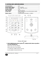
Page 8: ...x 82 x 19 mm Keypad type LED 16 status LEDs 4 mode LEDs GROUP ALARM SYSTEM PROG Button layout Standard telephone keypad 3 x 4 buttons Drawing 1 KP32 Keypad 1 FULLY ARMED mode arming symbol indicated...

Page 9: ...red 5 Partition input or output sabotage failure symbol indicated with diodes E partition P1 and 5 partition P2 Blinks quickly no longer present but there were failures sabotage of inputs or outputs a...

Page 10: ...on on the remote where Blinks alarm triggered in the past Lit continuously current alarm 15 SYSTEM diode When this diode is lit it means a system failure e g power failure battery failure ATS connecti...

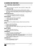
Page 11: ...nction button which enables switching between groups 28 Screw connectors Connectors for connecting cables leading from keypads to the alarm control 29 Cable entry hole A place for inserting connection...

Page 12: ...in the lower right corner of the display This means that the information is send to the alarm control panel The keypad transmits the entered characters as soon as any of the following conditions is me...

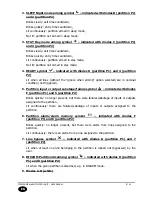
Page 13: ...transmission 3 Keypad buttons Buttons on the KP2W keypad function the same as on the KP32 keypad see section 3 KEYPAD KP32 SPECIFICATION points 17 to 27 After first pressing any button the keypad is b...

Page 14: ...KEYPAD SPECIFICATION Power supply 1 battery CR123A 3V Working time 3 years Frequency of operation 433 92 MHz Communication range up to 500m open air Communication one way Average current consumption 3...

Page 15: ...ministrator the user with the highest access level They can both arm and disarm the system as well as access and make changes in all user functions presented in chapter 9 User s Functions and its subs...

Page 16: ...e remote control If during the configuration of the remote control the arm immediately function was assigned to the any button pressing this button will fully arm immediately omitting time for exit 7...

Page 17: ...r the exit time passes 7 4 1 2 Sleep mode Arming partitions in sleep mode is sensible when the partition has at least one night line assigned whether switched off during the night or delayed In order...

Page 18: ...rol arming was assigned to the locked padlock button as the central enables assigning remote buttons to various functions it is possible to configure arming with a different button If exit time has be...

Page 19: ...FULL MODE SLEEP MODE STAY MODE 7 5 1 2 Quick arming with partition selection To arm the selected partitions without entering the code three button combinations can be used The table below shows method...

Page 20: ...odes and a long sound signal Additionally lit diodes 1 to 8 will indicate system errors This condition will last for 10 seconds If failures cannot be repaired quickly press to arm the system Pressing...

Page 21: ...in to blink depending on which partition the triggered spot was assigned to and which mode the system armed in e g blinking of diode 2 means that a detector assigned to partition two was triggered and...

Page 22: ...emote Press the remote button marked with the open padlock symbol assigned to the system disarming function NOTE it is assumed that during configuration of the remote disarming was assigned to the ope...

Page 23: ...42 EN 8 3 ALARM MUTE 1 To mute deactivate the alarm enter the code and press 3 beeps will confirm the code Also the system will be disarmed 2 In order to identify the alarm type please refer to 9 1 A...

Page 24: ...fter assigned delay time will cease to be shown on the keypad diodes will turn off The user will retain access to state of the alarm memory from inputs by entering the 3 function until he chooses to d...

Page 25: ...larm history If no diode is lit in the alarm history but the ALARM diode continues to blink it means that an alarm was triggered in the system by another source than an entry line You can access the O...

Page 26: ...B C and or D mean that inputs assigned to them are sabotaged Diodes switched off means there is no sabotage in the given group Switch between groups using the button To return to the main failure bran...

Page 27: ...ne blocking function allows de activating stand by mode of any zones or bypassing any damaged lines Also zones which are not in stand by mode and which the user has access to can be blocked Zones rema...

Page 28: ...to the monitoring station It can be enabled disabled by enter Administrator code Blinking of diode belonging to a group from A to D means that it is currently being shown To enable disable the chime...

Page 29: ...user has been added correctly you will hear a triple confirmation tone otherwise you will hear a continuous signal 9 7 ARMING ONLY USER CAN T DISARM THE SYSTEM This function disables the ability of se...

Page 30: ...the user to be deleted within your selected group group A B C or D numbers from 1 to 8 the number will start blinking and press to confirm or to exit without saving changes 4 If the user has been dele...

Page 31: ...igned to the partition which the user who entered the code has access to Diodes switch off when the corresponding detector is triggered By pressing the button the user can switch between groups and ch...

Page 32: ...rm Panic alarm activating the break in alarm Note for the emergency buttons to work it is necessary to be in arm disarm ready mode and wait at least 10 seconds since last 0 9 key press You can also pr...

Page 33: ...ts of commands are given in square brackets This means that they are optional fields Acquiring the state of partitions Command syntax XXXX GETARMED Command description Acquiring the information which...

Page 34: ...ber the numbers from 1 to 32 OUTPUT Setting the name of output corresponding to the indicated number the numbers from 1 to 3 USER Setting the name of user with the specified number the numbers from 1...

Page 35: ...indicated number the numbers from 1 to 32 OUTPUT Acquiring the name of output corresponding to the indicated number the numbers from 1 to 3 USER Acquiring the name of user with the specified number t...

Page 36: ...be send Example 1234 SETTELNUM 3 800123456 Feedback message description SETTELNUM OK command accepted SETTELNUM ERROR command rejected by the system Getting the phone number Command syntax XXXX GETTEL...

Page 37: ...the text message Example 1234 SETMESSAGE 4 Robbery Feedback message description SETMESSAGE OK command accepted SETMESSAGE ERROR command rejected by the system Getting the content of text message Comma...

Page 38: ...pter TELNUM ten digit chain of zeroes and ones Each digit counting from the left represents an index of the phone number first digit for the first phone number second digit for the second number and s...

Page 39: ...sage description GETUSERSMS EVENT TELNUM MSG_ID information about text message and phone number assinged to the event GETUSERSMS EVENT ERROR command rejected by the system Getting delay between disarm...

Page 40: ...s 1 32 INPUT1 TAMPEREND to INPUT32 TAMPEREND Sabotage of zones 1 32 ended INPUT1 LOCK to INPUT32 LOCK Bypass of zones 1 32 INPUT1 UNLOCK to INPUT32 UNLOCK Bypass of zones 1 32 ended OUTPUT1 ON to OUTP...

Page 41: ...arted KEYPAD FIRE END Fire alarm ended JAMMING BEGIN GSM jamming JAMMING END GSM jamming ended DETECTOR1 LOST to DETECTOR32 LOST Detector 1 32 signal lost DETECTOR1 OK to DETECTOR32 OK Detector 1 32 s...

Page 42: ...te Version Firmware Description 2017 09 20 v1 0 2 8 6 First version of the manual 2018 02 20 v1 2 2 9 1 Added chapters User categories Arming only user 2018 07 26 v1 3 2 10 0 Added a new response type...

Reviews: