TM_G
Tx1
1
6_R9A
GTC116, GTM116 - COMBINATION NETWORK TRANSMITTER
SETUP
The GTC116 Combination card option allows simultaneous analog outputs and RS-485 differential bus/line transceiver
outputs designed to integrate with various network protocols.
The GTM116 Combination Analog/Ethernet card option allows simultaneous analog outputs and full duplex IEEE 802.3
ethernet interface with automatic re-transmission on collision and cyclic redundancy checking on network data. An on-
board microcontroller performs over 7 million instructions per second to insure minimal network latency. Link status as
well as network activity are available via on-board LED indicators.
The GTC116 and GTM116 combination cards plug directly onto the main circuit board as shown in Figures 8 and 9.
GTC/GTM116 - ANALOG OUTPUT OUTPUT WIRING AND SETUP
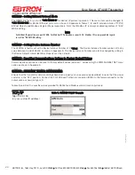
Analog output connections are made at the top left of the transmitter main circuit board OUTPUT connector as shown in
Figures 8 and 9. Independent 12-bit (4096 discrete states) linear analog outputs are provided for airflow at OUTPUT ter-
minal 1, and for temperature (or alarm) at OUTPUT terminal 2, each with over voltage and over current protection. Airflow
and temperature outputs are field selectable for either 0-5/0-10VDC or 4-20 mA. The OUTPUT terminal 2 can be
assigned as an Alarm output to provide an active high, active low or trouble alarm output. Outputs are galvanically iso-
lated from the main power supply to permit simple integration with virtually all building automation systems.
To wire the analog output signals, slide the cover plate up and off of the enclosure. Ensure that the power switch is in
the “OFF” position. Connect signal wires for airflow rate and temperature (or alarm) to the small, three position output
terminal labeled “OUTPUT” on the upper left hand side of the main circuit board as indicated in Figure 8. Airflow output
is at terminal 1, and temperature, airflow alarm or trouble alarm output is at terminal 2.
GTC116 - RS-485 NETWORK WIRING CONNECTIONS
Refer to Figure 8, and the following paragraph for network wiring considerations.
RS-485 Network Cable Specifications
The RS-485 network cable shall be shielded twisted pair with a characteristic impedance of 100 to 130 ohms.
Distributed capacitance between conductors shall be less then 100 pF per meter. Distributed capacitance between con-
ductors and shield shall be less then 200 pF per meter. The maximum recommended length of a network segment is
1200 meters with AWG 18 cable.
Connecting to an RS-485 Network:
Connect the NET+, NET- and COM terminals with shielded twisted pair cable meeting the specifications defined in the
previous paragraph (typically using two pairs, with one wire not used; one pair for +/- and [at least one of] the wires in
other pair for COM when using 2-pair cable). The connection to the network must be made in a "daisy chain” configura-
tion. "T" connections and stubs are NOT permitted. The shield should be terminated at one end on the network only.
*CAUTION
For ISOLATED output, the COM connection MUST BE CONNECTED to the network common for proper operation.
In addition, when the Analog Output is concurrently used with the RS-485 Output, the Common connection for
both Analog and RS-485 Outputs must be at the same potential.
For NON-ISOLATED output, the COM connection MUST BE CONNECTED to the common ground that is used by
the other network devices (typically the ground side of the 24VAC supply; the L2 terminal at the POWER connec-
tor block as shown in Figure 8). In addition, when the Analog Output is concurrently used with the RS-485
Output, the Common connection for both Analog and RS-485 Outputs must be at the same potential.
When configured for a 4-20mA output, the GTC116 is a “4-wire” device. The host controls shall not provide any excitation volt-
age to the output of the GTC116.
10
EBTRON
, Inc. 1663 Hwy. 701 S., Loris SC 29569
•
Toll Free: 800.2
EBTRON
(232.8766)
•
Fax: 843.756.1838
•
Internet:
EBTRON
.com
G
OLD
S
ERIES
GT
X
116 T
RANSMITTER
a measurable difference!
®


