ESC
ENTER
CONTRAST
REPLACE WITH
1.5 AMP
FAST ACTING ONLY
OUTPUT
1 2 COM
POWER
24VAC IN
L2 L1
ON
OFF
RS-485
NET COM
NET -
NET +
ON
TERM
F1
F2
VDC mA
OUT 1
OUT 2
RS-485
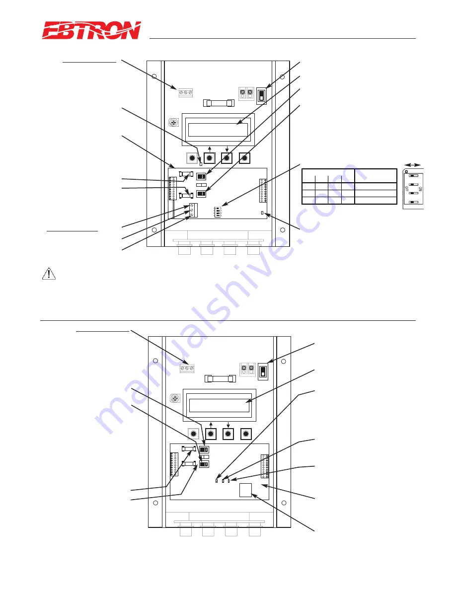
Analog Output Fuses
F1=OUT1
F2=OUT2
UL listed 0.125 Amp
P.N. 800-1105 (Qty:10)
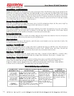
Transmitter Status LED
(Green 1 second flash normal;
2 second flash for fault)
Power Switch
COM*
NET
-
NET +
ANALOG OUTPUT
1: Airflow
2: Temperature/Alarm
COM: Common
(RS-485 output below)
*CAUTION
The common for the ANALOG and the RS-485 outputs must be at the same potential.
For ISOLATED RS-485 output, COM connection MUST BE CONNECTED to network common.
For NON-ISOLATED output, COM connection MUST BE CONNECTED to the common ground that other network devices are using (typically the
ground side of the 24VAC supply - L2 of the POWER terminals). Refer to RS-485 Network Wiring Connections paragraph for additional detail.
RS-485 Activity LED
.
(Green LED indicating RS-485 network activity).
SW1 (for OUT1)
Airflow - Output Signal Select
SW2 (for OUT2)
Temperature/Alarm/Trouble -
Output Signal Select
VDC: (0-5/0-10 VDC) or
mA: 4-20 mA
LCD Display
RS-485 OUTPUT
(For Analog Output, see
separate output above)
Combination Analog/
RS-485 Output Card
P.N. 800-1825
AC
TIV
ITY
TR
AFF
IC
LI
NK
D4
D3
D2
ETHERNET
10/100
VDC mA
S1
S2
F1
F2
ESC
ENTER
CONTRAST
REPLACE WITH
1.5 AMP
FAST ACTING ONLY
OUTPUT
1 2 COM
POWER
24VAC IN
L2 L1
ON
OFF
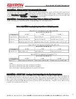
Combination Analog/ Ethernet
Output Card
P.N. 800-5026
LCD Display
ACTIVITY (green) indicates
Ethernet output board
health/status
(Green 1 second flash normal;
2 second flash for fault)
TRAFFIC (green) indicates
Ethernet traffic
LINK (green) indicates
Ethernet link status
Power Switch
RJ45 Ethernet Output
ANALOG OUTPUT
1: Airflow
2: Temperature/Alarm
COM: Common
(RJ45 Ethernet output below)
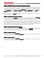
Analog Output Fuses
F1=OUT1
F2=OUT2
UL listed 0.125 Amp
P.N. 800-1105 (Qty:10)
SW1 (for OUT1)
Airflow Output Signal Select
SW2 (for OUT2)
Temperature/Alarm/Trouble -
Output Signal Select
VDC: (0-5/0-10 VDC) or
mA: 4-20 mA
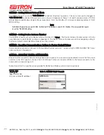
1
2
3
4
off
off
off
off
No Termination
off
oon
on
off
End of Line
on
off
off
oon
Fail-safe Bias
DIP Switch Position
TERMINATION DIP Switch
Network
Termination
OFF ON
Figure 9. GTM116 Combination Analog/Ethernet Transmitter Interior Detail
Figure 8. GTC116 Combination Analog/RS-485 Transmitter Interior Detail
SW3 TERMINATION Switch
11
EBTRON
, Inc. 1663 Hwy. 701 S., Loris SC 29569
•
Toll Free: 800.2
EBTRON
(232.8766)
•
Fax: 843.756.1838
•
Internet:
EBTRON
.com
G
OLD
S
ERIES
GT
X
116 T
RANSMITTER
a measurable difference!
®
TM_G
Tx1
1
6_R9A


