background image

Chengdu Ebyte Electronic Technology Co., Ltd.

E90-DTU(2G4L27)User Manual

Copyright ©2012–2020

,成都亿佰特电子科技有限公司

23

10. Operation notes

1. Please keep the warranty card of this equipment safely. The factory number (and important technical parameters) of

the equipment is on the warranty card, which has important reference value for future maintenance and new
equipment.

2. During the warranty period, if the radio is damaged due to the quality of the product itself, not caused by human

damage or lightning, please enjoy the free warranty. Please do not repair it yourself. If there is any problem, please
contact us. After sales service.

3. The device may not be operated in the vicinity of some flammable places (such as coal mines) or explosive

dangerous objects (such as detonators for detonators).

4. Appropriate DC stabilized power supply should be selected, which requires strong anti-high frequency interference,

small ripple, and sufficient load capacity; it also has functions such as overcurrent, overvoltage protection and
lightning protection to ensure data transmission.

5.

Do not use it in a working environment that exceeds the environmental characteristics of data transceiver, such as

high temperature, humidity, low temperature, strong electromagnetic field or dusty environment.

6. Do not let the data transceiver continuously be in full-load transmission state, otherwise the transmitter may be

burned out.

7. The ground wire of the data transceiver should be well connected with that of the external equipment (such as PC,

PLC, etc.) and of the power supply. Otherwise, it is easy to burn the communication interface; do not plug or unplug
the serial port when electrified.

8. When testing the data transceiver, it must be connected with a matching antenna or a 50Ω dummy load, otherwise it

will easily damage the transmitter; if the antenna is connected, the distance of the human body from the antenna
should preferably exceed 2 meters to avoid injury and cut. Do not touch the antenna while launching.

9. Wireless modem often have different communication distances in different environments. The communication

distance is often affected by temperature, humidity, obstacle density, obstacle volume, and electromagnetic
environment. In order to ensure stable communication, it is recommended to reserve, Communication distance
margin above50. %.

10. If the measured communication distance is not ideal, it is recommended to check the antenna quality and the

installation method of the antenna. You can also contact support@cdebyte.com for assistance.

11. Power supply is required to remain 50% of current, it should be noted that the ripple should not exceed 100mV.
12. Wireless communication products need to be connected with an impedance matching antenna to work properly, even

for short-term testing.

Summary of Contents for 2G4L27

Page 1: ...E90 DTU 2G4L27 ...

Page 2: ...5 1 Model specification 12 5 2 General specification paramet 12 5 3 Frequency and channel numbers 12 5 4 Current parameter 13 6 Function Description 14 6 1 Fixed Transmission Hexadecimal 14 6 2 Broadcast Transmission Hexadecimal 14 6 3 Broadcast Address 15 6 4 Monitor Address 15 6 5 Operating mode 15 7 Register read and write control 16 7 1 Command format 16 7 2 Register description 17 7 4 Configu...

Page 3: ...iber microwave and bright line it provides real time and reliable data transmission of monitoring signals in private networks under certain special conditions with low cost installation and maintenance It is convenient has strong diffraction ability flexible networking structure and long coverage It is suitable for occasions with many points and scattered complex geographical environment etc It ca...

Page 4: ...emperature range 40 C 85 C to adapt to a variety of harsh working environment All aluminum alloy casing compact size easy installation and good heat dissipation perfect shielding design with good electromagnetic compatibility and strong anti interference ability Multiple protection functions such as power reverse connection protection over current protection and antenna surge protection greatly in...

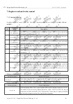
Page 5: ...rst install an antenna for the digital radio and then use USB to RS 232 or USB to RS 485 to connect the computer to the digital radio the radio M1 dials up M0 is arbitrary and enters the configuration mode The upper computer software is used to query and set the module parameters and the radio station needs to work in configuration mode The software interface is shown in the figure below ...

Page 6: ... selected filled in the parameter area have been written to the module 3 The parameter area is used with the Read Parameters button to display the current module parameters or to modify the parameters with the Write Parameters button to set the module parameters 4 Special commands for restarting and restoring factory settings are used to reset the module and restore the module parameters to the fa...

Page 7: ...logy Co Ltd E90 DTU 2G4L27 User Manual Copyright 2012 2020 Chengdu Ebyte Electronic Technology Co Ltd 6 3 Start two serial port debugging assistants select the baud rate 115200bps check mode as 8N1 to realize transparent transmission ...

Page 8: ...c Technology Co Ltd 7 4 If customer needs to modify the parameters please dial the switch in the configuration mode and connect to the computer Open the E90 DTU SL configuration software you can modify the relevant parameters After completing the configuration Mode 0 Factory default Mode 2 Parameter configuration ...

Page 9: ...WR LED Power LED Red lit when the power is on 4 LINK LED Data transceiver LED Yellow the connection is successful 5 DATA LED Serial data LED Yellow flashing during data transmission 6 DC power interface Power interface In line round hole outer diameter 5 5mm diameter 2 5mm 7 DIP switch Mode selection M1 upward dialing configuration mode when M0 is arbitrary M1 downward dialing transparent transmis...

Page 10: ...Chengdu Ebyte Electronic Technology Co Ltd E90 DTU 2G4L27 User Manual Copyright 2012 2020 Chengdu Ebyte Electronic Technology Co Ltd 9 单位 mm ...

Page 11: ...ce of the 5 5mm outer diameter 2 5mm diameter Also users can choose the VCC and GND terminal power supply from both are optional 8 28V DC power supply it is recommended to use 12V or 24V DC power supply for E90 DTU 4 2 RS232 The E90 DTU can be connected to the device via RS 232 using the standard DB 9 interface 4 3 RS485 E90 DTU can be connected to the 485_A terminal and 485_B terminal from with t...

Page 12: ... negative pole is connected to the system ground and the housing 3 485_B RS 485 interface interface B The RS 485 interface B is connected to the device interface B 4 485_A RS 485 interface interface A The RS 485 interface A is connected to the device interface A Note The transceiver will be in poor communication when connected to multiple devices it is recommended to be connected to a single devic...

Page 13: ...cker antenna over 2 meters height from the ground with the factory default parameters 5 2 General specification paramet No Item Value Note 1 Size 82 62 25 mm See more in Dimensions 2 Weight 130g 4 5g 3 Temperature 40 85 Meet industrial request 4 Antenna impedance 50Ω Standard 50 Ω characteristic impedance 5 Supply voltage 8 28V DC It is recommended to use 12V or 24V 6 Communication interface RS232...

Page 14: ...ter Model No Average emission current mA Waiting average current mA 12V 24V 12V 24V E90 DTU 2G4L27 226 110 22 15 Note 12V transient transmission MAX current 66mA 24V transient transmission MAX current 33mA it is recommended to reserve 50 MAX current margin when selecting the power supply which is beneficial to the long term stable operation of the radio ...

Page 15: ...hengdu Ebyte Electronic Technology Co Ltd E90 DTU 2G4L27 User Manual Copyright 2012 2020 成都亿佰特电子科技有限公司 14 6 Function Description 6 1 Fixed Transmission Hexadecimal 6 2 Broadcast Transmission Hexadecimal ...

Page 16: ...5 Operating mode The E90 DTU has two working modes In normal communication the radio is configured in the normal mode mode 0 the default setting of the radio is also the normal mode mode 0 Mode 0 3 M1 M0 Mode introduction Remark 0 Transmission mode ON ON Serial port open wireless open continuous transparent transmission Airspeed supports manual configuration and self adaptive automatic adjustment ...

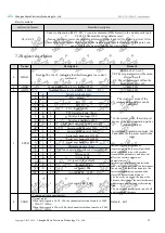
Page 17: ...module will enter a 10S clock configuration window period within which 10S clocks can configure the corresponding parameters of the module through the C0 command after the 10S clock is over the module uses the new parameters working 7 E3 E3 E3 In transparent transmission mode three E3s are sent in hexadecimal format and the corresponding module that receives this instruction will enter a 10S confi...

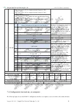
Page 18: ...tinuous transmission mode the baud rate of both parties must be the same 0 0 0 Serial port baud rate 1200 0 0 1 Serial port baud rate 4800 0 1 0 Serial port baud rate 9 600 default 0 1 1 Serial port baud rate 19200 1 0 0 Serial port baud rate 57600 1 0 1 Serial port baud rate 115200 1 1 0 Serial port baud rate 460800 1 1 1 Serial port baud rate 921600 2 1 0 Wireless air rate bps In the air rate no...

Page 19: ...will be checked before sending each packet of data If it is good send it directly If there is interference in the channel wait for the interference to disappear before sending Support for air speeds below 115200 which may affect the continuous transmission function after opening 0 Turn off LBT default 1 Open LBT 2 IO drive mode This bit is used to enable the internal pull up resistor of the module...

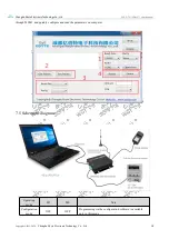
Page 20: ...ht 2012 2020 Chengdu Ebyte Electronic Technology Co Ltd 19 through M0M1 and quickly configure and read the parameters on computer 7 5 Schematic diagram Operating mode M1 M0 Note Configuration mode OFF OFF Programming via the configuration software is available only in this mode ...

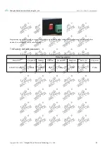
Page 21: ...ing can only be carried out in a specific working mode see the above table If the programming fails please confirm whether the working mode of the radio is correct 7 6 Factory default parameter Default parameter Model NO Frequency Address Channel Air data rate Baud rate Parity bit TX power E90 DTU 2G4L27 2 4GHz 0x0000 0x13 10kbps 9600 8N1 27dbm ...

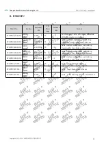
Page 22: ...nti inference E90 DTU 400SL30 RS232 RS485 433 470M 30 10 LoRa wireless configuration networking transmission long distance anti inference E90 DTU 900SL22 RS232 RS485 868 915M 22 5 LoRa wireless configuration networking transmission long distance anti inference E90 DTU 900SL30 RS232 RS485 868 915M 30 10 LoRa wireless configuration networking transmission long distance anti inference E90 DTU 170L30 ...

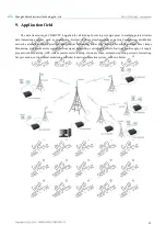
Page 23: ...of things transformation power load monitoring distribution network automation hydrological and hydrological forecasting water pipe network monitoring urban street lamps Monitoring air defense alarm control railway signal monitoring centralized control of railway water supply oil supply pipe network monitoring GPS system remote meter reading electronic crane automatic reporting seismic forecasting...

Page 24: ...the data transceiver continuously be in full load transmission state otherwise the transmitter may be burned out 7 The ground wire of the data transceiver should be well connected with that of the external equipment such as PC PLC etc and of the power supply Otherwise it is easy to burn the communication interface do not plug or unplug the serial port when electrified 8 When testing the data trans...

Page 25: ...al only provides electronic documents if necessary please go to our official website to download in addition if the user does not require special when the user orders in bulk We only provide product specifications according to a certain percentage of the order quantity Not every digital radio station is equipped with one by one please understand Revision history Version Date Description Issued by ...

Reviews: