background image

C

hengdu Ebyte Electronic Technology Co.,Ltd.

E01-2G4M27SX

User Manual

Copyright ©2012–2020

Chengdu Ebyte Electronic Technology Co.,Ltd.

3

2.

Specification and parameter

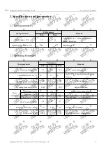
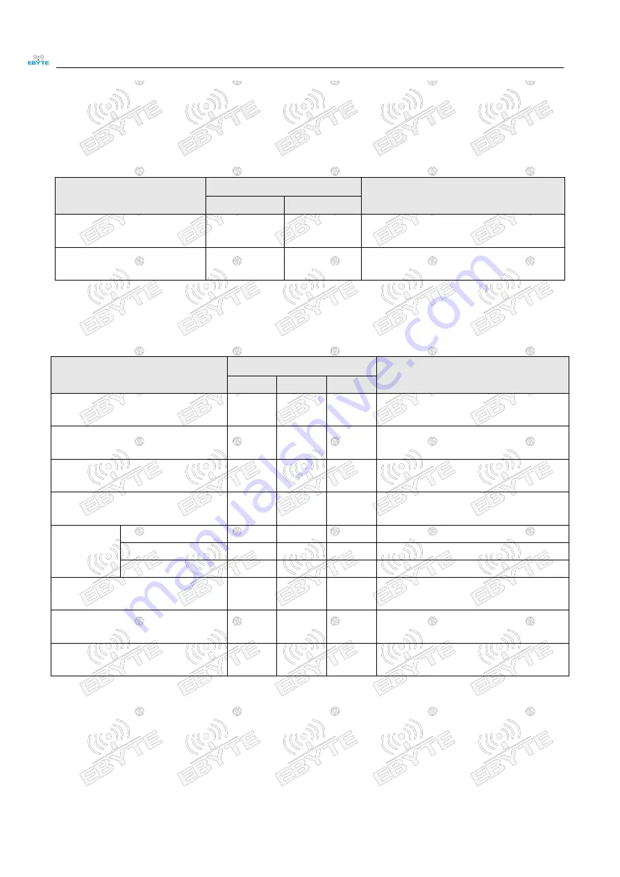
2.1 Limit parameter

Main parameter

Performance

Remark

Min.

Max.

Power supply

V

2.3

3.6

Voltage over 3.6 V will cause permanent
damage to module

Operating temperature

-40

+85

Industrial grade

2.2 Operating Parameter

Main parameter

Performance

Remark

Min.

Typ.

Max.

Operating voltage

V

2.3

3.3

3.6

≥3.3 V ensures output power

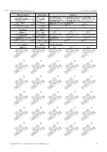
Communication level

V

-

3.3

-

For 5V TTL, it may be at risk of burning
down

Operating temperature

-40

-

+85

Industrial design

Operating frequency

GHz

2400

-

2525

Support ISM band

Power

consumption

TX current

mA

-

720

-

Instant power consumption

RX current

mA

-

23

-

-

Sleep current

μA

-

-

-

Does not support low power mode

Max Tx power

dBm

26

27

27

-

Receiving sensitivity

dBm

-113

-114

-115

Air data rate is 250 kbps

Air data rate

bps

250 k

-

2 M

Controlled via user’s programming

Summary of Contents for E01-2G4M27SX

Page 1: ...Chengdu Ebyte Electronic Technology Co Ltd E01 2G4M27SX User Manual Copyright 2012 2020 成都亿佰特电子科技有限公司 1 E01 2G4M27SX User Manual nRF24L01 2 4GHz 500mW SPI SMD wireless module ...

Page 2: ...ze and pin definition 5 4 Basic operation 6 4 1 Hardware design 6 4 2 Software writing 6 4 3 Power binning 7 5 Basic application 7 5 1 Basic circuit 7 6 FAQ 8 6 1 Communication range is too short 8 6 2 Module is easy to damage 8 6 3 BER Bit Error Rate is high 8 7 Welding operation guidance 9 7 1 Reflow soldering temperature 9 7 2 Reflow soldering curve 9 8 Related models 10 9 Antenna guidance 10 9...

Page 3: ...the MCU driver or use a dedicated SPI debugging tool 1 2 Features Ultra small volume only 18 14 5mm Maximum transmission power of 500mW software multi level adjustable Under ideal conditions the communication distance can reach 4 km Support global license free ISM 2 4GHz band Support air date rate of 2Mbps 1Mbps 250kbps 125 communication channels to meet the needs of multi point communication grou...

Page 4: ...g Parameter Main parameter Performance Remark Min Typ Max Operating voltage V 2 3 3 3 3 6 3 3 V ensures output power Communication level V 3 3 For 5V TTL it may be at risk of burning down Operating temperature 40 85 Industrial design Operating frequency GHz 2400 2525 Support ISM band Power consumption TX current mA 720 Instant power consumption RX current mA 23 Sleep current μA Does not support lo...

Page 5: ...ion Remark Distance for reference 4 km Test condition clear and open area antenna gain 5dBi antenna height 2 5m air data rate 250kbps FIFO 32 Byte Max length transmitted each time Crystal frequency 16 MHz Modulation GFSK Package SMD Connector 1 27 mm pin Communication interface SPI 0 10 Mbps Size 18 14 5 mm RF interface IPEX 50ohm impedance Weight 1 0 0 1g ...

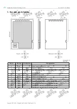
Page 6: ... Input Module control pin 3 CSN Input The chip select pin of the module is used to start an SPI communication 4 SCK Input Module SPI bus clock 5 MOSI Input Module SPI data input pin 6 MISO Output Module SPI data output pin 7 IRQ Output Module interrupt signal output low level is effective 8 GND Ground wire connect to power reference ground 9 GND Ground wire connect to power reference ground 10 GND...

Page 7: ...over the Bottom Layer or other layers which will affect the module s spurs and receiving sensitivity to varying degrees It is assumed that there are devices with large electromagnetic interference around the module that will greatly affect the performance It is recommended to keep them away from the module according to the strength of the interference If necessary appropriate isolation and shieldi...

Page 8: ...f nRF24L01 If the user needs to answer automatically the CE pin must maintain a high level during the transmission process instead of the high level time mentioned in the nRF24L01 manual greater than 10us The correct operation is CE 1 triggers the transmission After knowing that the transmission is completed it will set CE 0 instead of CE 0 after 10us The reason is after L01 transmission it will i...

Page 9: ...antenna quality or poor matching between antenna and module 6 2 Module is easy to damage Please check the power supply to ensure that it is between the recommended power supply voltage if exceeding the maximum value will cause permanent damage to the module Please check the stability of power source the voltage cannot fluctuate too much Please make sure antistatic measure are taken when installing...

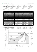
Page 10: ...t temperature max Tsmax Mx preheating temp 150 200 Preheat Time Tsmin to Tsmax ts Preheating time 60 120 sec 60 120 sec Average ramp up rate Tsmax to Tp Average ramp up rate 3 second max 3 second max Liquidous Temperature TL Liquid phase temp 183 217 Time tL Maintained Above TL Time below liquid phase line 60 90 sec 30 90 sec Peak temperature Tp Peak temp 220 235 230 250 Aveage ramp down rate Tp t...

Page 11: ...enna recommendation Antennas are an important role in the communication process Often inferior antennas will have a great impact on the communication system Therefore our company recommends some antennas as matching antennas with excellent performance and reasonable price Model NO Type Frequency Gain Size Feeder Connector Feature Hz dBi mm cm TX2400 NP 5010 Flexible 2 4G 2 0 10x50 IPEX Flexible FP...

Page 12: ...istory Version Date Remark By 1 0 2020 05 19 First version About us Technical support support cdebyte com Documents and RF Setting download link www ebyte com Thank you for using Ebyte products Please contact us with any questions or suggestions info cdebyte com Fax 028 64146160 Web www ebyte com Address B5 Mould Industrial Park 199 Xiqu Ave High tech Zone Chengdu Sichuan China ...

Reviews: