Chengdu Ebyte Electronic Technology Co.,Ltd.
Copyright ©2012–2020
,
Chengdu Ebyte Electronic Technology Co., Ltd
7
weakened.
4.2 Software editing
The drive mode of this module PA+LNA is completely equivalent to SI24R1, and users can operate
according to the SI24R1 chip manual (see SI24R1 manual for details);
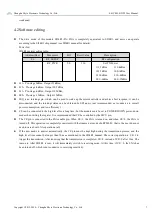
Power bin:
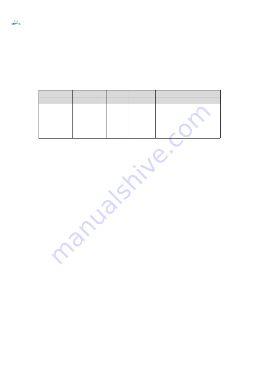
SI24R1 register setting table:
Address(Hex)
Mnemonic
Bit
Reset Value
Description
06
RF_SETUP
RF configuration
RF_PWR
2:0
110
Set TX Power
111:7dBm
110:4dBm
101:3dBm
100:1dBm
011:0dBm
010:-4dBm
001:-6dBm
000:-12dBm
011
:
Pre-stage 0dBm
,
Output 21dBm
;
010
:
Pre-stage -4dBm
,
Output 20.5dBm
;
011
:
Pre-stage -6dBm
,
Output 19.5dBm;
000
:
Pre-stage -12dBm
,
Output 15dBm;
IRQ is an interrupt pin, which can be used to wake up the microcontroller and achieve fast response; it can be
disconnected, and the interrupt status can be obtained by SPI query (not recommended, not conducive to overall
power consumption, and low efficiency);
CE can be connected to the high level for a long time, but the module must be set to POWER DOWN power-down
mode when writing the register. It is recommended that CE be controlled by the MCU pin;
The CE pin is connected to the LNA enable pin. When CE=1, the LNA is turned on, and when CE=0, the LNA is
turned off. This operation is completely consistent with the transceiver mode of nRF24L01; that is, the user does not
need to care about LNA operation at all;
If the user needs to answer automatically, the CE pin must be kept high during the transmission process, and the
high level time cannot be longer than 10us as mentioned in the SI24R1 manual. The correct operation is: CE=1 to
trigger the transmission. After knowing that the transmission is completed, CE=0, instead of CE=0 after 10us. The
reason is: After SI24R1 is sent, it will immediately switch to receiving mode. At this time, if CE= 0, the LNA has
been turned off, which is not conducive to receiving sensitivity.


