


Chengdu Ebyte Electronic Technology Co., Ltd.
E180-ZG120B-TB User Manual
Copyright ©2012–2019
,
Chengdu Ebyte Electronic Technology Co., Ltd.
3
Description
:
No.
Pin
Description
1
AVDD
Module power port, 3.3V power
supply is recommended
2
3.3V
Baseboard LDO output 3.3V, can
supply power to the module
3
TXD
TXD of cp2102
4
RXD
RXD of cp2102
5
PA1
RXD of the module
6
PA0
TXD of the module
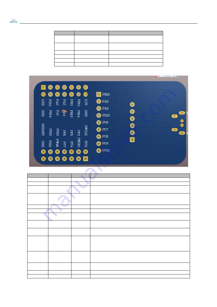
No.
Name
Direction
Function
1
GND
-
Ground, connected to power supply reference ground
2
GND
-
Ground, connected to power supply reference ground
3
PD13
Input
TOUCHLINK pin, which is continuously pulled lower than 3000ms,
will initiate a ZLL network establishment or join request
4
PD14
Input
WAKE pin is mainly used to wake up the sleep terminal. It is high level
when powered on. When the pin is pulled low externally, the sleep
terminal device will be woken
5
PA0(TX)
Output
Serial port transmission port TX
6
PA1(RX)
Input
Serial port receiving port RX
7
PA2
Input/Outp
ut
Reserve
8
PA4
Input/Outp
ut
Reserve
9
PB11
Input
Operating mode switching pin. When the pull-low time is longer than
500ms, the operating mode is switched.
10
PB12
Input
UART_BAUD_RESET pin is used to reset the device baud rate. The
power-on default is high level. In any mode, if this pin is pulled lower
for more than 1000ms, the serial port parameters of the module will be
restored to the default 115200.
11
PB13
Output
ACK pin is used to indicate the last user data transmission status. This
pin is pulled low before the transmission is started, and the pin is pulled
high after the transmission.
12
PB14(GPIO0)
Input/Outp
ut
GPIO Input/ Output port 0
13
3.3V
-
Module power supply positive reference voltage, voltage range
14
GND
-
Ground, connected to power supply reference ground


