background image

Chengdu Ebyte Electronic Technology Co., Ltd.

E22-xxxT22S series product user manual

Copyright©2012–2024

, Chengdu Ebyte Electronic Technology Co., Ltd.

22

7.4 Factory default parameters

model

E22-230T22S factory default parameter values: C0 00 09 00 00 00 63 00 28 03 00 00

E22-400T22S factory default parameter value: C0 00 09 00 00 00 62 00 17 03 00 00

E22-900T22S factory default parameter value: C0 00 09 00 00 00 62 00 12 03 00 00

Model No

Frequency

Address

Channel

Air data rate

Baud rate

Parity format

Transmit

Power

E22-230T22S

230.125MHz

0x0000

0x28

2.4kbps

9600

8N1

22dbm

E22-400T22S

433.125MHz

0x0000

0x17

2.4kbps

9600

8N1

22dbm

E22-900T22S

868.125MHz

0x0000

0x12

2.4kbps

9600

8N1

22dbm

8. AT command

Parameter configuration or query using AT commands needs to be done in configuration mode;

AT commands are used in configuration mode. AT commands are divided into three categories: command
commands, setting commands and query commands;

Users can query the AT command set supported by the module through "AT+HELP=?". The baud rate used by
the AT command is 9600 8N0;

When the input parameters exceed the range, they will be restricted. Please do not let the parameters exceed
the range to avoid unknown situations.

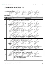
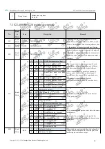
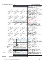
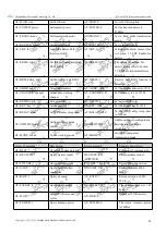
8.1 AT command list

Command Commands

Description

Example

Example description

AT+IAP

(use with caution,

please see 8.3 Precautions for
Serial Port Firmware Upgrade
in this article for details )

Enter IAP upgrade mode AT+IAP

Enter IAP upgrade mode

AT+RESET

Device restart

AT+RESET

Device restart

AT+DEFAULT

Restore configuration
parameters to default
and the device restarts

AT+DEFAULT

Restore configuration
parameters to default
and the device restarts

Setting Commands

Description

Example

Example description

AT+UART=baud,parity

Set baud rate and parity

AT+UART=3,0

Set the baud rate to 9600, 8N0

AT+RATE=rate

Set air data rate

AT+RATE=7

Set air data rate to 62.5K

/

15.6K

AT+PACKET=packet

Set packet length

AT+PACKET=0

Set the packet size to 240 bytes

Summary of Contents for E22 T22S Series

Page 1: ...gdu Ebyte Electronic Technology Co Ltd E22 xxxT22S series product user manual Copyright 2012 2024 Chengdu Ebyte Electronic Technology Co Ltd 1 E22 xxxT22S User Manual AT command 22dBm LoRa wireless mo...

Page 2: ...ing Address 11 5 5 Module Reset 11 5 6 Detailed explanation of AUX 11 5 6 1 Indication of Serial port data output 11 5 6 2 Indication of Wireless transmission 11 5 6 3 The module is being configured 1...

Page 3: ...2 Modules are easily damaged 28 12 3 BER Bit Error Rate is high 29 13 Welding Operation Guidance 29 13 1 Reflow soldering temperature 29 13 2 Reflow soldering curve 30 14 Related Models 30 15 Antenna...

Page 4: ...rights in estoppel or other ways whether express or implied The test data obtained in the article are all obtained by the Ebyte laboratory and the actual results may vary slightly We hereby declared...

Page 5: ...ctrum modulation technology it brings longer communication distance and stronger anti interference ability Supporting serial port upgrade of firmware making it more convenient to update firmware Suppo...

Page 6: ...ecurity alarm and remote keyless entry Smart home and industrial sensors etc Wireless alarm security system Building automation solutions Wireless industrial grade remote control healthcare products A...

Page 7: ...mption 22dBm Receiving current mA 15 15 17 Sleep current uA 3 3 3 Software shutdown temperature Operating temperature 40 85 Industrial grade design Storage temperature 40 85 Industrial grade design 2...

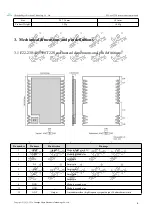
Page 8: ...l dimensions and pin definitions 3 1 E22 230 400 900T22S mechanical dimensions and pin definitions Pin number Pin name Pin direction Pin usage 1 NRST Input Module reset pin 3 3V 2 GND Module ground wi...

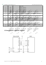
Page 9: ...t used 21 M1 Input very weak pull up Work with M0 to decide 4 working modes of the module cannot be left floating can be grounded if not used 22 RXD Input TTL serial port input connected to the extern...

Page 10: ...ction Description 5 1 Fixed point Transmission 5 2 Broadcast Transmission 5 3 Broadcasting Address For Example Set the address of module A to 0xFFFF and the channel to 0x04 When module A is used as a...

Page 11: ...r the module to work normally 5 6 Detailed explanation of AUX AUX Pin can be used as indication for wireless TX RX buffer and self check It can indicate whether there is data not transmitted via wirel...

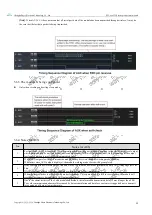
Page 12: ...ondition is met AUX will outputs high level 2 When AUX outputs low level it means the module is busy it won t conduct working mode checking Within 1ms since AUX outputs high level the module working m...

Page 13: ...switching At this time the switching mode operation is invalid the module will process all the user data before performing the new mode detection Therefore the general recommendation is to detect the...

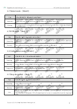
Page 14: ...can be received normally and the receiving function is equivalent to that in mode 0 6 4 Configuration mode Mode 2 type When M0 0 M1 1 the module works in mode 2 Transmitting Wireless transmission is t...

Page 15: ...ers E g 1 Read channel command starting address length parameter Send C1 05 01 Returen C1 05 01 09 E g 2 Read module address network address serial port and air data rate Send C1 00 04 Return C1 00 04...

Page 16: ...the data blocking and possible data loss caused by the same baud rate It is generally recommended that both communication parties have the same baud rate 0 0 0 Serial port baud rate 1200 0 0 1 Serial...

Page 17: ...are this bit will be turned off automatically If you don t want to use the M0 M1 pins to switch working modes you can enable this function and use specific serial port commands to switch modes Format...

Page 18: ...ke up can be modified The default time is 0 1 To modify the delay time after wake up WOR receiver needs to send the command C0 09 02 03 E8 in the configuration mode C0 is writing command 09 is the sta...

Page 19: ...munication parties have the same baud rate 0 0 0 Serial port baud rate 1200 0 0 1 Serial port baud rate 2400 0 1 0 Serial port baud rate 4800 0 1 1 Serial port baud rate 9600 default 1 0 0 Serial port...

Page 20: ...C2 C3 02 00 to switch to transparent transmission mode Send C0 C1 C2 C3 02 01 to switch to WOR mode Send C0 C1 C2 C3 02 02 to switch to configuration mode Send C0 C1 C2 C3 02 03 to switch to sleep mo...

Page 21: ...2 is the length 03 E8 is the set delay the maximum delay FFFF is 65535ms if the delay is set to 0 the wake up delay is turn off 2 Data can be sent within the delay 0 WOR receiver default Working in WO...

Page 22: ...ories command commands setting commands and query commands Users can query the AT command set supported by the module through AT HELP The baud rate used by the AT command is 9600 8N0 When the input pa...

Page 23: ...nnel Set module working channel AT CHANNEL 23 Set frequency to 433 125M AT NETID netid Set network ID AT NETID 2 Set network ID to 2 AT KEY key Set module key AT KEY 1234 Set the module key to 1234 AT...

Page 24: ...Note 1 0 22dBm 1 20dBm 2 17dBm 3 14dBm Mode transmission mode 0 transparent 1 fixed point Router repeater mode 0 Close 1 Open AT TRANS Query sending mode AT TRANS 1 Return to fixed point mode AT ROUTE...

Page 25: ...eed to keep Power on and wait 60 seconds the program will automatically exit otherwise it will enter the upgrade mode indefinitely even if it is restarted After entering the upgrade mode the baud rate...

Page 26: ...fore Repeater 2 can forward the data of Repeater 1 to the network NETID 05 Thus node 3 and node 4 can receive the data from node Node 4 outputs data normally but no ourput from Node3 because Node 3 ha...

Page 27: ...cimal 11 Hardware Design It is recommended to use a DC regulated power supply to power the module The power supply ripple coefficient should be as small as possible and the module must be reliably gro...

Page 28: ...f damage Try to stay away from some TTL protocols whose physical layer is also 2 4GHz such as USB3 0 The antenna installation structure has a great impact on module performance Make sure the antenna i...

Page 29: ...ply Poor quality or too long extension cords and feeders can also cause a high bit error rate 13 Welding Operation Guidance 13 1 Reflow soldering temperature Reflow soldering curve characteristics Lea...

Page 30: ...e mm Communication Interface E22 230T22S SX1262 230M 22 5 SMD 16 26 TTL E22 230T30S SX1262 230M 30 10 SMD 20 40 5 TTL E22 400T22S SX1262 433 470M 22 5 SMD 16 26 TTL E22 400T30S SX1262 433 470M 30 10 S...

Page 31: ...raight omnidirectional TX433 JZG 6 Rubber antenna 433M SMA J 2 5 62 Short straight omnidirectional TX433 JW 5 Rubber antenna 433M SMA J 2 0 50 Flexible omnidirectional TX433 JWG 7 Rubber antenna 433M...

Page 32: ...n Revision date Revision Notes Maintenance man 1 0 2023 6 15 initial version Hao About Us Technical support support cdebyte com Documents and RF Setting download link https www cdebyte com Thank you f...

Reviews: