background image

Chengdu Ebyte Electronic Technology Co,;Ltd


      E32-170T30D user manual   


Copyright ©2012–2019

Chengdu Ebyte Electronic  Technology Co.,Ltd.


10 


5.6.4 Notes for AUX 

No. 

Description 

For function 1 & function 2  mentioned above, the priority should be given to the one with low level output, 
which  means if it  meets each of any low level output condition, AUX outputs low level,  if none of the low 
level condition is met, AUX outputs high level. 

When  AUX  outputs  low  level,  it  means  the  module  is  busy  &  cannot  conduct  operating  mode  checking. 
Within 1ms since AUX  outputs high level, the mode switch will  be completed. 

After switching to new operating mode, it will not work in the new  mode immed iately until AUX rising edge 
lasts for 2ms  . If AUX stays on the high level,  the operating mode switch can be affected immediately. 

When the user switches to other operating modes from  mode 3 (sleep  mode) or it ’s still in reset process, the 
module will  reset user parameters, during which AUX outputs low level. 


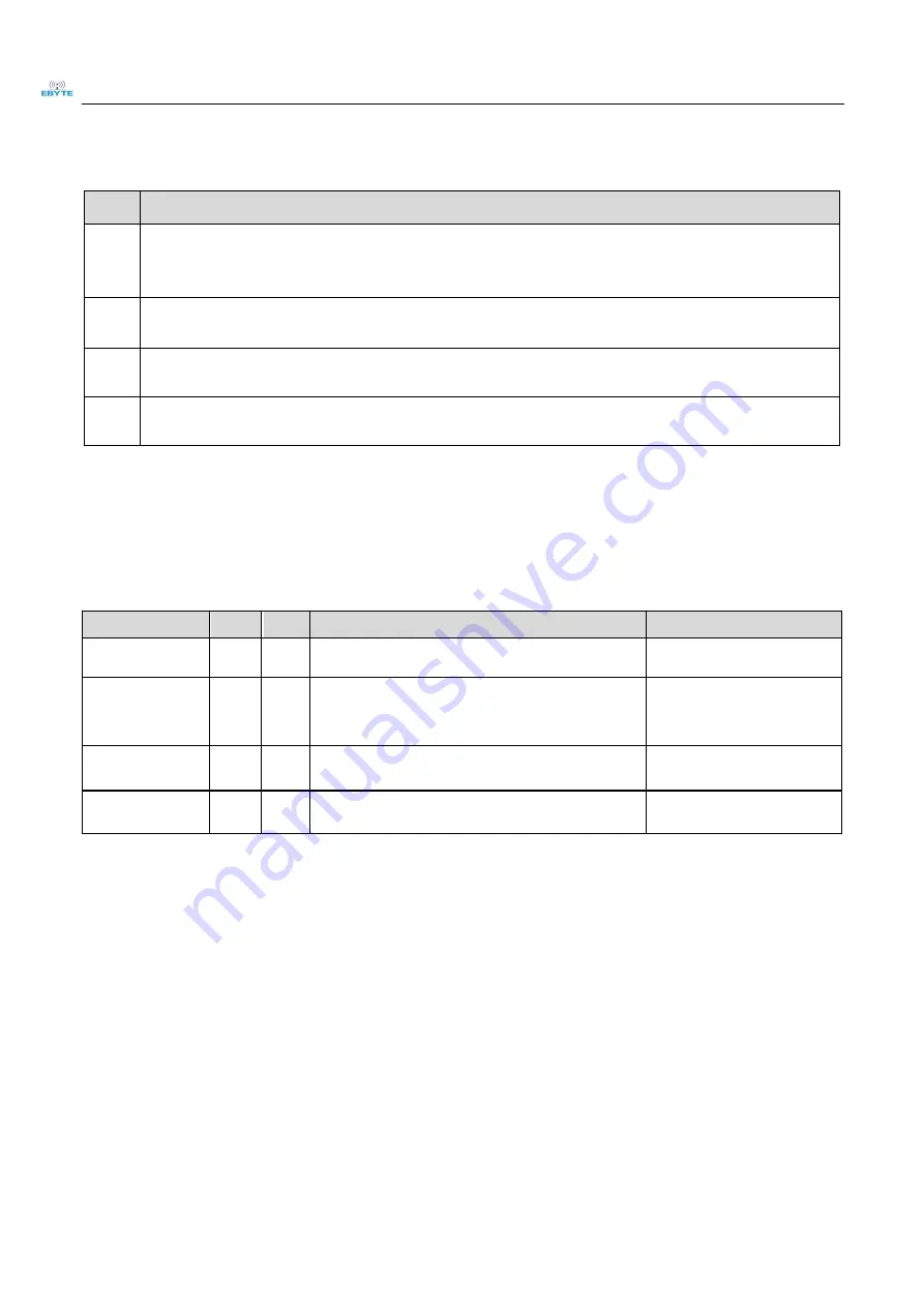
6 Operating mode 

There are four operating modes, which are set by M1 and M0, the details are as follows: 

Mode

0-3


M0


M1


Mode introduction


Remark


0 Normal 

UART  and  wireless  channel  are  open,  transparent 
transmission is on 

The  receiver  must  work  in 
mode 0 or mode 1 

1 Wake up 

UART  and  wireless  channel  are  open,  the  only 
difference with mode 0 is that before transmitting data, 
increasing the wake up code automatically, so that it can 
awake the receiver  under mode 3. 

The receiver could be 0,1 or 2 

2 Power 

saving 

UART  close,  wireless  is  under  air-awaken  mode,  after 
receiving  data, UART open and send data. 

transmitter  must  be  mode  1, 
unable to transmit in this mode. 

3 Sleep 

sleep  mode,  receiving  parameter  setting  command  is 

available. 

more  details  on  parameter 

specification. 

6.1


Mode switch 


The user can decide the operating  mode by the co mb ination of M1 and M0. The two  GPIO of MCU can be used to 

switch mode. After  modify ing M1 or M0,  it will start to work in new  mode 1ms later  if the module  is free. If there 

are  any  serial  data  that  are  yet to  finish  wireless  transmitting,  it  will  start  to  work  in  new  mode  after  the  UART 

transmitting  fin ished. After the  module receives the wireless data & transmits the data through serial port,  it  will 

start  to  work  in  new  mode  after  the  transmitting  finished.  Therefore,  the  mode-switch  is  only  valid  when  AUX 

outputs 1, otherwise it will  delay. 


For example, in mode 0 or mode 1, if the user inputs massive data consecutively and switches operating mode at the 

same time, the  mode-switch operation is  invalid.  New  mode checking can only be started after all the user’s data 

process  completed.  It  is  recommended  to  check AUX  p in  out  status  an d  wait  2ms  after A UX  outputs  high  level 

before switching the mode. 

Summary of Contents for E32-170T30D

Page 1: ...E32 170T30D User Manual SX1278 170MHz 1W DIP Wireless Module ...
Page 2: ...1 FIXED TRANSMISSION 7 5 2 BROADCASTINGTRANSMISSION 7 5 6 1 Indication of UART output 8 5 6 2 Indication of wireless transmitting 9 5 6 3 Configuration procedure of module 9 5 6 4 Notes for AUX 10 6 OPERATING MODE 10 6 1 MODE SWITCH 10 6 2 NORMAL MODE MODE 0 11 6 3 WAKE UP MODE MODE 1 12 6 4 POWER SAVING MODE MODE 2 12 6 5 SLEEP MODE MODE 3 12 7 COMMAND FORMAT 13 7 1 DEFAULT PARAMETERS 13 7 2 READ...

Page 3: ...19 Chengdu Ebyte Electronic Technology Co Ltd 2 9 1 COMMUNICATION RANGE ISTOO SHORT 17 9 2 MODULE IS EASY TO DAMAGE 17 9 3 BER BIT ERROR RATE IS HIGH 18 10 PRODUCTION GUIDANCE 18 11 E32 SERIES 18 12 ANTENNA RECOMMENDATION 19 13 PACKAGE FOR BATCH ORDER 19 REVISION HISTORY 20 ABOUT US 20 ...

Page 4: ...It is in stable bulk production and are widely applied in utility meters IoT renovation smart home etc The modules feature data encryption and compression The data transmitted in air features randomness The encryption decryption algorithm makes data interception meaningless And the data compression enables shorter transmitting time and lower rate of being interfered which increased the reliability...

Page 5: ...e used in short distance Operating temperature 40 85 2 2 Operating parameter Main parameter performance Notes Min Typ Max Operating voltage V 3 3 5 0 5 2 5 0 V ensures output power Communication level V 3 3 For 5V TTL it may be at risk of burning down Operating temperature 40 85 Industrial design Operating frequency MHz 160 173 Support ISM band Power consumptio n Transmitting current mA 680 Instan...

Page 6: ... Ebyte Electronic Technology Co Ltd 5 antenna height 2 5m air data rate 2 4kbps TX length 58 Byte Maximum capacity of single package Buffer 512 Byte Modulation LoRa Communication interface TTL 3 3V Package DIP Connector 2 54mm Size 24 43mm Antenna SMA K 50 ohm impedance 3 Size and pin definition ...

Page 7: ...igured as open drain or pull up input 4 TXD Output TTLUART outputs connects to external RXD MCU PC input pin Can be configured as open drain or push pulloutput 5 AUX Output To indicate module s working status wakes up the external MCU During the procedure of self check initialization thepin outputs low level Can be configured as push pulloutput suspendingis allowed 6 VCC Input Power supply 2 3 5 2...

Page 8: ...er manual Copyright 2012 2019 Chengdu Ebyte Electronic Technology Co Ltd 7 5 Function description 5 1 Fixed transmission 5 2 Broadcasting transmission 5 3 Broadcasting address For example Set the address of module A as 0xFFFF or 0x0000 and the channel as 0x04 ...

Page 9: ...owered AUX outputs low level immediately conducts hardware self check and sets the operating mode based on user s parameters During the process the AUX remains low level After the process completed the AUX outputs high level and starts to work as per the operating mode combined by M1 and M0 Therefore users need to wait the AUX rising edge as the start of module s normal work 5 6 AUX description AU...

Page 10: ...ithout overflow Buffer not empty when AUX 0 the internal 512 bytes data in the buffer have not been written to the RFIC completely If the user starts to transmit data at this circumstance it may cause overtime when the module is waiting for the user data or transmitting wireless sub package When AUX 1 it does not mean that all the UART data of the module have been transmitted already perhaps the l...

Page 11: ...UART and wireless channel are open the only difference with mode 0 is that before transmitting data increasing the wake up code automatically so that it can awake thereceiver under mode 3 The receiver could be 0 1 or 2 2 Power saving 0 1 UART close wireless is under air awaken mode after receiving data UART open and send data transmitter must be mode 1 unable to transmit in this mode 3 Sleep 1 1 s...

Page 12: ... consumption of the whole sys tem have been reduced and the efficiency of whole systemis largely improved 6 2 Normal mode mode 0 When M1 0 M0 0 module works in mode 0 Transmitti ng The module can receive the user data via serial port and transmit wireless data package of 58 bytes When the data inputted by user is up to 58 byte the module will start wireless transmission During which the user can i...

Page 13: ...reless module monitors thepreamble code at regular time Once it gets the preamble code it will remain as receiving status and waiting for the completion of receiving the entire valid data package Then theAUX outputs low level 5ms later theserial port is open to transmit received wireless data through TXD Finally AUX outputs high level after process completed The wireless module stays in power savi...

Page 14: ...4 Three C3 are sent in hexadecimal format The module returns the version information and they must be sent in succession 7 1 Default parameters Default parameter values C0 00 00 1A 17 44 Model Frequency Address Channel Air data rate Baud rate Parity Transmitting power E32 170T30D 170MHz 0x0000 0x28 2 4kbps 9600 8N1 1W 7 2 Reading operating parameters Instruction format Description C1 C1 C1 In slee...

Page 15: ...s this frame data is control command Must be0xC0 or 0xC2 C0 Save theparameters when power down C2 Do not save theparameters when power down 1 ADDH High address byteof module the default 00H 00H FFH 2 ADDL Low address byteof module the default 00H 00H FFH 3 SPED 7 6 UART parity bit UART mode can be different between communication parties 0 0 8N1 default 0 1 8O1 1 0 8 E1 1 1 8N1 equal to 00 5 4 3 TT...

Page 16: ...ginal setting after complete the process 0 Transparent transmission mode 1 Fixed transmission mode 6 IO drive mode default 1 This bit is used to the module internal pull up resistor It also increases the level s adaptability in case of open drain But in some cases it may need external pull up resistor 1 TXD and AUX push pulloutputs RXD pull up inputs 0 TXD AUX open collector outputs RXD open colle...

Page 17: ...ll as possible and the module needs to be reliably grounded Please pay attention to the correct connection of the positive and negative poles of the power supply Reverse connection may cause permanent damage to the module Please check the power supply to ensure it is within the recommended voltage otherwise when it exceeds the maximum value the module will be permanently damaged Please check the s...

Page 18: ...he antenna is exposed preferably vertically upward When the module is mounted inside the case use a good antenna extension cable to extend the antenna to the outside The antenna must not be installed inside the metal case which will cause the transmission distance to be greatly weakened 9 FAQ 9 1 Communication range is too short The communication distance will be affected when obstacle exists Data...

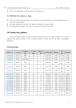
Page 19: ...32 series Model No Core IC Frequency Hz Tx power dBm Distance km Air Data Rate Package Size mm Interface E32 868T20S SX1276 868M 20 3 0 3k 19 2k SMD 16 26 UART E32 915T20S SX1276 915M 20 3 0 3k 19 2k SMD 16 26 UART E32 400T20S SX1278 433M 470M 20 3 0 3k 19 2k SMD 16 26 UART E32 915T30S SX1276 915M 30 8 0 3k 19 2k SMD 25 40 3 UART E32 868T30S SX1276 868M 30 8 0 3k 19 2k SMD 25 40 3 UART E32 433T30S...

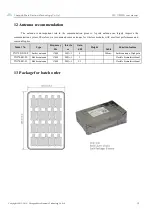
Page 20: ...y improve the communication system Therefore we recommend some antennas for wireless modules with excellent performance and reasonable price Model No Type Frequency Hz Interfa ce Gain dBi Height Cable Function feature TX170 XP 200 Sucker antenna 170M SMA J 4 200cm Sucker antenna High gain TX170 JK 20 Rubber antenna 170M SMA J 3 Flexible omnidirectional TX170 JK 11 Rubber antenna 170M SMA J 2 5 Fle...

Page 21: ... E32 915T20S E32 400T20S huaa 1 30 2018 01 22 Updating E32 868T20D E32 868T30D E32 915T20D E32 915T30D E32 170T30D huaa 1 40 2018 05 24 Updating antenna option huaa 1 50 2018 10 11 Manual dividing huaa About us Technical support support cdebyte com Documents and RF Setting download link www ebyte com Thank you for using Ebyte products Please contact us with any questions orsuggestions info cdebyte...

Reviews: