background image

Chengdu Ebyte Electronic Technology Co,;Ltd

E32-433T20DT user manual

Copyright ©2012–2019

Chengdu Ebyte Electronic Technology Co.,Ltd.

16

parts with large electromagnetic interference.

High-frequency digital routing, high-frequency analog routing, and power routing must be avoided under the
module. If it is necessary to pass through the module, assume that the module is soldered to the Top Layer, and the
copper is spread on the Top Layer of the module contact part(well grounded), it must be close to the digital part of
the module and routed in the Bottom Layer

Assuming the module is soldered or placed over the Top Layer, it is wrong to randomly route over the Bottom Layer
or other layers, which will affect the module's spurs and receiving sensitivity to varying degrees

It is assumed that there are devices with large electromagnetic interference around the module that will greatly
affect the performance. It is recommended to keep them away from the module according to the strength of the
interference. If necessary, appropriate isolation and shielding can be done

Assume that there are traces with large electromagnetic interference (high-frequency digital, high-frequency analog,
power traces) around the module that will greatly affect the performance of the module. It is recommended to stay
away from the module according to the strength of the interference. If necessary, appropriate isolation and shielding
can be done.

If the communication line uses a 5V level, a 1k-5.1k resistor must be connected in series (not recommended, there is
still a risk of damage)

Try to stay away from some physical layers such as TTL protocol at 2.4GHz , for example: USB3.0

The mounting structure of antenna has a great influence on the performance of the module. It is necessary to ensure
that the antenna is exposed, preferably vertically upward. When the module is mounted inside the case, use a good
antenna extension cable to extend the antenna to the outside

The antenna must not be installed inside the metal case, which will cause the transmission distance to be greatly
weakened.

9 FAQ

9.1 Communication range is too short

The communication distance will be affected when obstacle exists.

Data lose rate will be affected by temperature, humidity and co-channel interference.

The ground will absorb and reflect wireless radio wave, so the performance will be poor when testing near ground.

Sea water has great ability in absorbing wireless radio wave, so performance will be poor when testing near the sea.

The signal will be affected when the antenna is near metal object or put in a metal case.

Power register was set incorrectly, air data rate is set as too high (the higher the air data rate, the shorter the
distance).

The power supply low voltage under room temperature is lower than 2.5V, the lower the voltage, the lower the
transmitting power.

Due to antenna quality or poor matching between antenna and module.

Summary of Contents for E32-433T20DT

Page 1: ...E32 433T20DT User Manual SX1278 433MHz 100mW DIP Wireless Module...

Page 2: ...1 FIXED TRANSMISSION 6 5 2 BROADCASTING TRANSMISSION 7 5 6 1 Indication of UART output 8 5 6 2 Indication of wireless transmitting 8 5 6 3 Configuration procedure of module 9 5 6 4 Notes for AUX 9 6 O...

Page 3: ...9 Chengdu Ebyte Electronic Technology Co Ltd 2 9 1 COMMUNICATION RANGE IS TOO SHORT 16 9 2 MODULE IS EASY TO DAMAGE 17 9 3 BER BIT ERROR RATE IS HIGH 17 10 PRODUCTION GUIDANCE 17 11 E32 SERIES 17 12 A...

Page 4: ...features randomness The encryption decryption algorithm makes data interception meaningless Data compression enables shorter transmitting time and lower rate of being interfered which increases the r...

Page 5: ...at risk of burning down Operating temperature 40 85 Industrial design Operating frequency MHz 410 525 Support ISM band Power consumptio n Transmitting current mA 106 Instant power consumption Instant...

Page 6: ...nded 2 M1 Input weak pull up Work with M0 to decide 4 working modes of module not suspended if not used could be grounded 3 RXD Input TTL UART inputs connects to external MCU PC TXD output pin Can be...

Page 7: ...tput suspending is allowed 6 VCC Input Power supply 2 3 5 2V DC 7 GND Input Ground 8 Fixed orifice Fixed orifice 9 Fixed orifice Fixed orifice 10 Fixed orifice Fixed orifice 4 Connect to MCU No Descri...

Page 8: ...of module A as 0xFFFF or 0x0000 and the channel as 0x04 When module is the transmitter transparent transmission all modules under channel 0x04 will receive the data the purpose of broadcast is realize...

Page 9: ...re are data that are not sent yet via wireless way or whether all wireless data has been sent through UART or whether the module is still in the process of self check initialization 5 6 1 Indication o...

Page 10: ...UX outputs low level if none of the low level condition is met AUX outputs high level 2 When AUX outputs low level it means the module is busy cannot conduct operating mode checking Within 1ms since A...

Page 11: ...id when AUX outputs 1 otherwise it will delay For example in mode 0 or mode 1 if the user inputs massive data consecutively and switches operating mode at the same time the mode switch operation is in...

Page 12: ...ule working in mode 0 can only be received by the module working in mode 0 or 1 Receiving The wireless receiving function of the module is on the data packet transmitted from the module working in mod...

Page 13: ...orking parameters through specific instruction format pls refer to parameters setting for details Notes When the mode changes from stand by mode to others the module will reset its parameters during w...

Page 14: ...nd yy refers to the other module features 7 4 Reset command Instruction format Description C4 C4 C4 In sleep mode M0 1 M1 1 User gives the module instruction HEX format C4 C4 C4 the module resets for...

Page 15: ...Specifications Except for E32 400T20S 4 CHAN 7 6 5 reserved Write 0 Communication channel 00H 1FH correspond to 410 441MHz 4 0 channel 410M CHAN 1M default 17H 433MHz 5 OPTION 7 Fixed transmission ena...

Page 16: ...iency 0 0 20dBm default 0 1 17dBm 1 0 14dBm 1 1 10dBm For example The meaning of No 3 SPED byte The binary bit of the byte 7 6 5 4 3 2 1 0 Configures by user 0 0 0 1 1 0 1 0 Meaning UART parity bit 8N...

Page 17: ...he interference If necessary appropriate isolation and shielding can be done If the communication line uses a 5V level a 1k 5 1k resistor must be connected in series not recommended there is still a r...

Page 18: ...r or too long so the bit error rate is high 10 Production guidance This type is full sized module when the welder welds the module he must be welding according to the anti static regulation This produ...

Page 19: ...2 43 8 9 5mm Soft inside FPC soft antenna TX433 JW 5 Rubber antenna 433M SMA J 2 50mm Flexible omnidirectional TX433 JWG 7 Rubber antenna 433M SMA J 2 5 75mm Flexible omnidirectional TX433 JK 20 Rubbe...

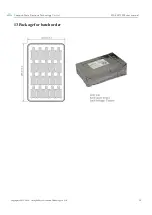
Page 20: ...Chengdu Ebyte Electronic Technology Co Ltd E32 433T20DT user manual Copyright 2012 2019 Chengdu Ebyte Electronic Technology Co Ltd 19 13 Package for batch order...

Page 21: ...2 915T20S E32 400T20S huaa 1 30 2018 01 22 Updating E32 868T20D E32 868T30D E32 915T20D E32 915T30D E32 170T30D huaa 1 40 2018 05 24 Updating antenna option huaa 1 50 2018 10 11 Manual dividing huaa A...

Reviews: