background image

Chengdu Ebyte Electronic Technology Co., Ltd

E32-900T20S User Manual

Copyright ©2012–2021

Chengdu Ebyte Electronic Technology Co.,Ltd.

14

6.4

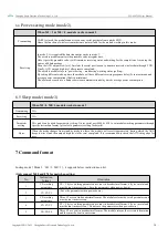
Power-saving mode (mode 2)

When M1 = 1 & M0 = 0, module works in mode 2

Transmitting

UART is closed, the module cannot receive any serial port data from outside MCU.

Hence the function of wireless transmission is not available for the module working in this mode.

Receiving

In mode 2, it is required the data transmitter works in mode 1.

The wireless module monitors the preamble code at regular time.

Once it gets the preamble code, it will remain as receiving status and waiting for the completion of receiving the

entire valid data package.

Then the AUX outputs low level, 5ms later the serial port is open to transmit received wireless data through TXD.

Finally, AUX outputs high level after process completed.

The wireless module stays in “power-saving – monitoring” working status (polling).

By setting different wake-up time, the module will have different receiving response delay (2s in maximum) and

average power consumption (30uA in minimum).

The user needs to achieve a balance between communication delay time & average power consumption.

6.5 Sleep mode (mode 3)

When M1=1, M0=1, module works in mode 3

Transmitting

N/A

Receiving

N/A

Parameter

setting

This mode can be used for parameter setting. It uses serial port 9600 & 8N1 to set module working parameters through

specific instruction format. (pls refer to parameters setting for details)

Notes

When the mode changes from stand-by mode to others, the module will reset its parameters, during which the AUX

keeps low level and then outputs high level after reset completed. It is recommended to check the AUX rising edge for

user.

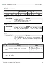
7 Command format

In sleep mode

Mode 3

M1=1, M0=1

, it supports below instructions on list.

(Only support 9600 and 8N1 format when setting)

No.

Instruction

format

Illustration

1

C0+working

parameters

C0 + 5 bytes working parameters are sent in hexadecimal format. 6 bytes in total and

must be sent in succession, ( Save the parameters when power-down ).

2

C1+C1+C1

( Save the parameters when power-down )

3

C2+working

parameters

Three C1 are sent in hexadecimal format. The module returns the saved parameters and

must be sent in succession.

4

C3+C3+C3

C2 + 5 bytes working parameters are sent in hexadecimal format. 6 bytes in total and

must be sent in succession. ( Do not save the parameters when power-down )

5

C4+C4+C4

Three C3 are sent in hexadecimal format. The module returns the version information

and they must be sent in succession.

Summary of Contents for E32-900T20S

Page 1: ...E32 900T20S User Manual SX1276 868MHz 915MHz SMD Wireless Module ...

Page 2: ...N DESCRIPTION 9 5 1 FIXED TRANSMISSION 9 5 2 BROADCASTING TRANSMISSION 9 5 3 BROADCASTING ADDRESS 9 5 4 MONITOR ADDRESS 10 5 5 RESET 10 5 6 AUX DESCRIPTION 10 5 6 1 Indication of UART output 10 5 6 2 Indication of wireless transmitting 11 5 6 3 Configuration procedure of module 11 5 6 4 Notes for AUX 11 6 OPERATING MODE 12 6 1 MODE SWITCH 12 6 2 NORMAL MODE MODE 0 13 6 3 WAKE UP MODE MODE 1 13 6 4...

Page 3: ...4 RESET COMMAND 15 7 5 PARAMETER SETTING COMMAND 15 8 BASIC OPERATION 17 8 1 HARDWARE DESIGN 17 9 FAQ 18 9 1 COMMUNICATION RANGE IS TOO SHORT 18 9 2 MODULE IS EASY TO DAMAGE 19 9 3 BER BIT ERROR RATE IS HIGH 19 10 PRODUCTION GUIDANCE 19 10 1 REFLOW SOLDERING TEMPERATURE 19 10 2 REFLOW SOLDERING CURVE 20 11 PACKAGE FOR BATCH ORDER 20 REVISION HISTORY 21 ABOUT US 21 ...

Page 4: ...duction use modification or disclosure to third parties of this document or any part thereof without the express permission of EBYTE is strictly prohibited The information contained herein is provided as is and EBYTE assumes no liability for the use of the information No warranty either express or implied is given including but not limited with respect to the accuracy correctness reliability and f...

Page 5: ...rrection to improve communication stability Air wake up ultra low power consumption suitable for battery applications Adopt industrial grade active temperature compensated crystal oscillator to ensure its stability and consistency The maximum transmit power is 20dBm and the software is multi level adjustable Support 868 915MHz EU general frequency band The data transmission rate of 0 3k 19 2kbps 2...

Page 6: ... in utility meters IoT renovation smart home etc The modules feature data encryption and compression The data transmitted in air features randomness air Data Rate Default 2 4kps E32 900T20S strictly follows design standards of FCC CE CCC and meets various RF certification requirements for exporting 1 2 Application Home security alarm and remote keyless entry Smart home and industrial sensors Wirel...

Page 7: ...wer consumpti on Transmitting current mA 120 Instant power consumption Receiving current mA 16 Turn off current μA 4 Software is shut down Max Tx power dBm 20 Receiving sensitivity dBm 123 Air data rate is 2 4kbps Main parameter Description Remark Distance for reference 5500m Test condition clear and open area antenna gain 5dBi antenna height 2 5m air data rate 2 4kbps TX length 58 Byte Maximum ca...

Page 8: ... Empty Pin 4 NC Empty Pin 5 NC Empty Pin 6 NC Empty Pin 7 NC Empty Pin 8 GND Ground 11 GND Ground 12 ANT Antenna 13 GND Ground 14 GND Ground 15 GND Ground 16 GND Ground 19 GND Ground 20 M0 Input weak pull up Work with M1 to decide 4 working modes of module not suspended if not used could be grounded 21 M1 Input weak pull up Work with M0 to decide 4 working modes of module not suspended if not used...

Page 9: ... connects to external RXD MCU PC input pin 24 AUX Output Used to indicate the working status of the module The user wakes up the external MCU and outputs low level during power on self check initialization can be left floating 25 VCC Power supply 2 3 5 5V DC 26 GND Ground 4 Connect to MCU No Description STM8L MCU 1 The UART module is TTL level 2 For some MCU works at 5VDC it may need to add 4 10K ...

Page 10: ...er Manual Copyright 2012 2021 Chengdu Ebyte Electronic Technology Co Ltd 9 5 Function description 5 1 Fixed transmission 5 2 Broadcasting transmission 5 3 Broadcasting address For example Set the address of module A as 0xFFFF or 0x0000 and the channel as 0x04 ...

Page 11: ...owered AUX outputs low level immediately conducts hardware self check and sets the operating mode based on user s parameters During the process the AUX remains low level After the process completed the AUX outputs high level and starts to work as per the operating mode combined by M1 and M0 Therefore users need to wait the AUX rising edge as the start of module s normal work 5 6 AUX description AU...

Page 12: ...uffer not empty when AUX 0 the internal 512 bytes data in the buffer have not been written to the RFIC completely If the user starts to transmit data at this circumstance it may cause overtime when the module is waiting for the user data or transmitting wireless sub package When AUX 1 it does not mean that all the UART data of the module have been transmitted already perhaps the last packet of dat...

Page 13: ...Power saving 0 1 UART close wireless is under air awaken mode after receiving data UART open and send data Transmitter must be mode 1 unable to transmit in this mode 3 Sleep 1 1 sleep mode receiving parameter setting command is available More details on parameter specification 6 1Mode switch The user can decide the operating mode by the combination of M1 and M0 The two GPIO of MCU can be used to s...

Page 14: ...ess than 58 bytes the module will wait 3 byte time and treat it as data termination unless continuous data inputted by user Then the module will transmit all the data through wireless channel When the module receives the first data packet from user the AUX outputs low level After all the data are transmitted into RF chip and transmission start AUX outputs high level At this time it means that the ...

Page 15: ...tion 6 5 Sleep mode mode 3 When M1 1 M0 1 module works in mode 3 Transmitting N A Receiving N A Parameter setting This mode can be used for parameter setting It uses serial port 9600 8N1 to set module working parameters through specific instruction format pls refer to parameters setting for details Notes When the mode changes from stand by mode to others the module will reset its parameters during...

Page 16: ...turns its present version number for example C3 00 45 0A 14 0B XX YY The third bytes means frequency 45 here means frequency 900MHZ 0x14 means 20dBm power xx is the version number and yy refers to the other module features 7 4 Reset command Instruction format Description C4 C4 C4 In sleep mode M0 1 M1 1 User gives the module instruction HEX format C4 C4 C4 the module resets for one time During the...

Page 17: ... data rate must keep the same for both communication parties 0 0 0 0 3k 0 0 1 1 2k 0 1 0 2 4k default 0 1 1 4 8k 1 0 0 9 6k 1 0 1 19 2k 1 1 0 19 2k same to 101 1 1 1 19 2k same to 101 General Specifications 4 CHAN 7 6 5 reserved Write 0 Communication channel 00H 45H correspond to 862 931MHz 4 0 channel 862M CHAN 1M default 06H 868MHz 5 OPTI ON 7 Fixed transmission enabling bit similar to MODBUS In...

Page 18: ...s about turn on or turn off FEC 0 Turn off FEC 1 Turn on FEC default 1 0 Transmission power approximation The external power must make sure the ability of current output more than 250mA and ensure the power supply ripple within 100mV Low power transmission is not recommended due to its low power supply efficiency 0 0 20dBm default 0 1 17dBm 1 0 14dBm 1 1 10dBm For example The meaning of No 3 SPED ...

Page 19: ...he performance It is recommended to keep them away from the module according to the strength of the interference If necessary appropriate isolation and shielding can be done Assume that there are traces with large electromagnetic interference high frequency digital high frequency analog power traces around the module that will greatly affect the performance of the module It is recommended to stay ...

Page 20: ...der too high or too low temperature 9 3 BER Bit Error Rate is high There are co channel signal interference nearby please be away from interference sources or modify frequency and channel to avoid interference Poor power supply may cause messy code Make sure that the power supply is reliable The extension line and feeder quality are poor or too long so the bit error rate is high 10 Production guid...

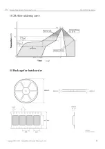
Page 21: ...Chengdu Ebyte Electronic Technology Co Ltd E32 900T20S User Manual Copyright 2012 2021 Chengdu Ebyte Electronic Technology Co Ltd 20 10 2 Reflow soldering curve 11 Package for batch order ...

Page 22: ...Date Description Issued by 1 00 2021 5 13 Initial version Linson About us Technical support support cdebyte com Documents and RF Setting download link www ebyte com Thank you for using Ebyte products Please contact us with any questions or suggestions info cdebyte com Fax 028 64146160 Web www ebyte com Address B5 Mould Park 199 Xiqu Ave Chengdu Sichuan China ...

Reviews: