Chengdu Ebyte Electronic Technology Co.,Ltd.
Copyright ©2012–2019
,
Chengdu Ebyte Electronic Technology Co.,Ltd.
6
20
NC
Input/Output
NC pin, this pin needs to be left floating (for subsequent expansion)
21
NC
Input
download port
--VCC
(Hanging, users do not need to pay attention)
22
NC
Input
download port
–SWDIO
(Hanging, users do not need to pay attention)
23
GND
Input
download port
--GND
(Hanging, users do not need to pay attention)
24
NC
Input
download port
--SWCLK
(Hanging, users do not need to pay attention)
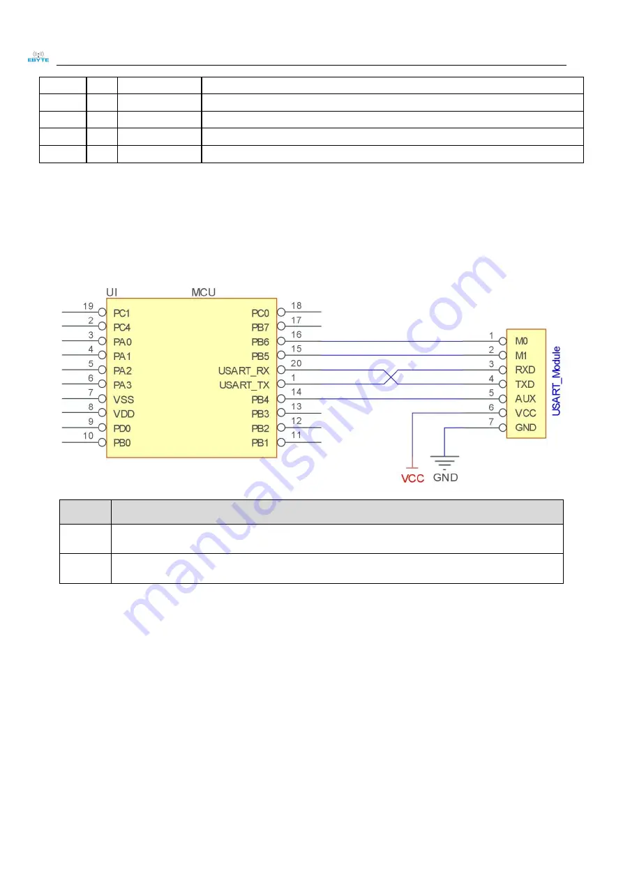
Ⅳ Recommended wiring diagram
Serial
Number
A brief description of the connection between the module and the microcontroller (the above picture
takes the STM8L microcontroller as an example)
1
The wireless serial port module is TTL level, please connect with TTL level MCU.
2
Some 5V microcontrollers may need to add 4~10K pull-up resistors to the TXD and AUX pins of the
module.
Ⅴ Detailed function
5.1 Module reset
After the module is powered on, AUX will output a low level immediately, perform hardware self-test, and set
the working mode according to user parameters. During this process, the AUX keeps the low level, and after the
completion, the AUX outputs the high level, and starts to work normally according to the working mode formed by
the combination of M1 and M0. Therefore, the user needs to wait for the rising edge of AUX as the starting point
for the normal operation of the module.


