background image

Chengdu Ebyte Electronic Technology Co.,Ltd

E851-RTU(4440-ETH) User Manual

Copyright ©2012–2019, Chengdu Ebyte Electronic Technology Co.,Ltd

23

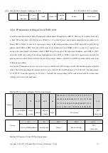
The corresponding Modbus register of the switch automatic reporting setting is 40082 (0x0051), and the value corresponds to the

function:

Switch off automatic reporting function

Switching quantity is automatically reported and transmitted via RS485

Switching quantity is automatically reported and transmitted via GPRS Network

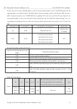
The switch change upload protocol is as follows. The frame headers is 0xAA and 0xBB are fixed, and the values range of DI1, DI2,

DI3, and DI4 are 0x00, 0x01, and 0xFF, while

0x00 represents the switch input disconnection.

0x01 represents the switch input closed.

0xff represents that the switch input has not changed.

The values of DI1, DI2, DI3, and DI4 in the table indicate that the DI1, DI2 status is updated to open, the DI3 status is updated to

closed, and the DI4 status is unchanged. The last two bytes are modbus CRC16 calculated values.

Frame header

DI1

DI2

DI3

DI4

Modbus CRC

0xAA 0xBB

0x00

0x00

0x01

0xff

0xBD 0xDA

4.3.3. DO Time Settings for Switch Output

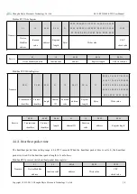
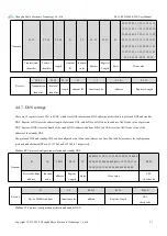
The setting of switching pulse output time is to set the switching output time (relay NO, COM closing time). The corresponding

Modbus register is 40083 (0x0052). Its value range is 300-65535 Ms. If the value is less than 300 ms, the default switching output is

closed to hold state, that is, the switching output is kept after closing.

If it is set to 300ms or more, such as 500 ms, after sending the closing command, the closing of the switch will be maintained 500 ms,

and then it will be automatically disconnected after 500 ms.

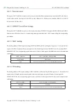
4.3.4. Switch DO Restart Output State Settings

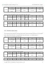
Whether the device restarts to maintain the state before the power is turned off or to maintain the setting of the specific output

state,This function is only valid if the output time of the device switch is set to register value less than 300 ms.

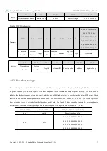
The corresponding Modbus register is 40085 (0x0054) when the switch restart output state is set, Its value range is 0x00-0x10.

When this register value is 0x10, the last switch output state is maintained after the power is turned off and restarted; When the register

value is 0x00-0x0F, the output state of the device restart switch is determined by the low four bits. Bit 4 corresponds to DO4, Bit 3

corresponds to DO3, Bit 2 corresponds to DO2, Bit 1 corresponds to DO1, When power on, DO4, DO2 are in closed state (relay NO,

COM closed) DO3, DO1 is in open state (relay NO, COM disconnected), corresponding register value is 0000 1010, that is, 0xa0, "1"

is closed state, "0" is disconnected state.

Summary of Contents for E851-RTU

Page 1: ...E851 RTU 4440 ETH User Manual...

Page 2: ...rking mode 14 4 1 1 Slave mode 14 4 1 2 Host mode 15 4 2 Basic functions of IO 16 4 2 1 Switch DO Output 16 4 2 2 Read switch DI input 18 4 2 3 Read analog AI input 19 4 2 4 Analog AI range setting 21...

Page 3: ...TCP RTU protocol Support connection to Ebyte cloud command control Support two working modes host mode slave mode slave can connect to multiple devices through RS485 Support reload touch button long...

Page 4: ...tions please refer to the following chapters 1 1 Port connection 1 1 1 RS485 connection Note When the 485 bus high frequency signal is transmitted the signal wavelength is shorter than the transmissio...

Page 5: ...onic Technology Co Ltd E851 RTU 4440 ETH User Manual Copyright 2012 2019 Chengdu Ebyte Electronic Technology Co Ltd 4 1 1 2 Switch Input Connection 1 1 3 Relay output connection 1 1 4 Differential ana...

Page 6: ...Ltd 5 1 2 Quick Use Wiring Computer connects to E851 RTU 4440 ETH via USB to RS485 Networking Plug the network cable into the RJ45 port Power supply E851 RTU 4440 ETH working voltage is DC 8 28V 1 2...

Page 7: ...yright 2012 2019 Chengdu Ebyte Electronic Technology Co Ltd 6 At this time the device address of the current device can be seen and the auto refresh processing can be performed and the switch output c...

Page 8: ...input default trunk connection 4 way differential analog input and 4 way relay output Support Modbus TCP RTU protocol The product is highly user friendly and users can easily and quickly integrate in...

Page 9: ...opyright 2012 2019 Chengdu Ebyte Electronic Technology Co Ltd 8 Software parameters Network Type Ethernet Configuration command Modbus TCP RTU Network protocol Modbus TCP RTU Working mode Host mode Sl...

Page 10: ...cted with device B interface 5 RS485 A RS485 interface A RS485 interface A is connected with device A interface 6 RS485 G Signal reference can be unconnected 7 DIG Switching input Can be used in pairs...

Page 11: ...Cooperate with common end of relay 3 32 COM 3 Relay 3 Common End Cooperate with the normally open closed pin of relay 3 33 NO 3 Normally open pin of Relay 3 Cooperate with common end of relay 3 34 NC...

Page 12: ...ss table function code 0x01H 0x05H 0x0FH 0x03H 0x06H 0x10H Register address Register quantity Register attribute Register type Register value range Support function code 00017 0x0010 1 DO1 Switch Outp...

Page 13: ...rotocol type UDP TCP Read write 0 1 40124 0x007B 22 Custom registration package Read write 40146 0x0091 1 Registration package mechanism Read write 0 4 40147 0x0092 22 Heartbeat package Read write 401...

Page 14: ...ud Rate Code Table 0 1200 1 2400 2 4800 3 default 9600 4 19200 5 38400 6 57600 7 115200 3 4 RS485 serial port check bit value table check bit value table 0 default No check 1 even parity check 2 Odd p...

Page 15: ...to the device by the network or 485 terminal sender satisfies the Modbus RTU Modbus TCP protocol and the address in the data is the device address and the device will reply with the same protocol If t...

Page 16: ...the device address and the device responds to the sender with the same protocol If the data sent by the network or 485 bus to the device does not satisfy the Modbus RTU Modbus TCP protocol or satisfy...

Page 17: ...n coil is energized the phenomenon is opposite relay NC port and COM port are disconnected NO port and COM port are closed with a value of 1 Query relay status by instruction Example Read the 4 way sw...

Page 18: ...are closed NO port and COM port are disconnected coil is energized relay NC port and COM port are disconnected NO port and COM port are closed The state of relay is controlled by command Example Func...

Page 19: ...ch Quantity Bytes Write value Receive 00 01 00 00 00 06 01 0F 00 11 00 02 Transmission identifier Protocol identifier length element ID Function code Switching address Write Switch Quantity 4 2 2 Read...

Page 20: ...ssion identifier Protocol identifier length element ID Function code Return bytes Switch Input Value 4 2 3 Read analog AI input Function code 03 read holding register 04 read input register Address ra...

Page 21: ...nput assuming AI1 input is 9946uA the corresponding value should be 0x0x26DA Modbus RTU protocol reads differential analog input Transmit 01 04 00 10 00 01 30 0F Device ModBus address Function code An...

Page 22: ...f more than 10 ms then to open state completing a pulse count 4 3 1 1 Read pulse count value Function code 03 read hold register Address range 40049 0x0030 40052 0x0033 Description The maximum pulse c...

Page 23: ...ld be 0x0a corresponding to the binary value of 0000 1010 Modbus RTU protocol clear pulse count value Transmit 01 06 00 40 00 0a 08 19 Device ModBus address Function code Address Write value CRC check...

Page 24: ...NO COM closing time The corresponding Modbus register is 40083 0x0052 Its value range is 300 65535 Ms If the value is less than 300 ms the default switching output is closed to hold state that is the...

Page 25: ...value 00 0D 31 31 36 2E 36 32 2E 34 32 2E 31 39 32 Port 31687 corresponding to hexadecimal 7BC7 The protocol type TCP UDP is saved using the protocol register the value 0x0001 corresponds to the TCP...

Page 26: ...tion package can be ASCII code or hex the length of hex cannot be greater than 20 bytes and the length of ASCII code cannot be greater than 40 bytes Transmit 01 10 00 63 00 18 30 00 0D 31 31 36 2E 36...

Page 27: ...146 0x0091 type length Register package value Registered Packet Mechanism 00 01 00 0A 41 42 43 44 45 46 47 48 49 4A 00 00 00 00 00 00 00 00 00 00 00 00 00 00 00 00 00 00 00 00 00 00 00 00 00 00 00 00...

Page 28: ...et can be ASCII code or hex the length of hex cannot be greater than 20 bytes and the length of ASCII code cannot be greater than 40 bytes The first register of the heartbeat packet is used to store t...

Page 29: ...01 10 00 92 00 16 2C 00 00 00 0A 00 01 02 03 04 05 06 07 08 09 00 00 00 00 00 00 00 00 00 00 00 00 00 00 00 00 00 00 00 00 00 00 00 00 00 00 00 00 00 00 Transmission identifier Protocol identifier len...

Page 30: ...value 4 4 5 Heartbeat packet mode The heartbeat packet mode is divided into a serial heartbeat packet and a network heartbeat packet the default is a network heartbeat packet When writing 0 to this r...

Page 31: ...0XD2 a total of 11 registers are stored in the gateway address where 0XC8 stores the length of the gateway address and 0XC9 to 0XD2 stores the ASCII code value of the gateway address You can use 10 f...

Page 32: ...d DNS and standby DNS Register 0xD3 stores the address length of preferred DNS and 0xD4 to 0xDD stores the address ASCII code value of preferred DNS Register 0XDE stores the length of the standby DNS...

Page 33: ...ssion function is turned on The default is Cloud Transfer Closed 4 4 9 Clear cache Register 0xAF can set whether to clear the cache in the network SOKET support 0x0003 0x0006 0x0010 function code When...

Page 34: ...er reading is 40232 0x00E9 and the total length of register is 11 wherein the first register is the MAC length and the second register to the eleventh register stores the MAC value For example MAC B2F...

Page 35: ...are and software of the product this specification may be changed without further notice Ultimately the latest version of the specification shall prevail Revision History Version Date Description Issu...

Reviews: