background image

Chengdu Ebyte Electronic Technology Co., Ltd.

Distributed IO Host (M31 Series) User Manual

Copyright © 2012 , Chengdu Ebyte Electronic Technology Co., Ltd.

3

2.2. Device connection

2.2.1. RS485 connection

Note:

When the 485 bus high-frequency signal is transmitted, the signal wavelength is shorter than the transmission line. The signal will form a reflected

wave at the end of the transmission line, interfering with the original signal. Therefore, it is necessary to add a terminal resistor at the end of the transmission line

to prevent the signal from being reflected after it reaches the end of the transmission line. The terminal resistor should be the same as the impedance of the

communication cable, with a typical value of 120 ohms. Its function is to match the bus impedance and improve the anti-interference and reliability of data

communication.

Summary of Contents for M31 Series

Page 1: ...1 M31 Series Distributed IO Host User Manual...

Page 2: ...7 3 Technical index 8 3 1 Parameters 8 3 2 Device default parameters 9 3 3 Dimensions 10 3 4 LED indicator light description 10 3 5 Port and button description 17 3 6 DIP switch 25 4 Product function...

Page 3: ...Chengdu Ebyte Electronic Technology Co Ltd Distributed IO Host M31 Series User Manual Copyright 2012 Chengdu Ebyte Electronic Technology Co Ltd 2 5 2 Parameter configuration 38 6 Revision History 39...

Page 4: ...s customers to access the current on site environment the modules are self contained With status diagnosis function it can monitor the communication status of IO modules in real time it can support a...

Page 5: ...yte Electronic Technology Co Ltd 2 2 Quick to use Note This experiment needs to be conducted with the default factory parameters 2 1 Equipment preparation The following table shows the materials requi...

Page 6: ...al will form a reflected wave at the end of the transmission line interfering with the original signal Therefore it is necessary to add a terminal resistor at the end of the transmission line to preve...

Page 7: ...tronic Technology Co Ltd 4 2 2 2 AI connection Note AI is used with the COM side of adjacent wireframe selection 2 2 3 DI connection Note DI only supports 12V 24V input 2 2 4 DO connection Note 1 A si...

Page 8: ...g the network cable into the RJ45 port and connect to the PC Power supply Use DC 12V switching power supply DC 9 36 V to power M31 AAAX4440G 2 3 Parameter configuration Step 1 Modify the IP address of...

Page 9: ...ronic Technology Co Ltd 6 Step 2 Open the network assistant select TCP client enter the remote host IP 192 168 3 7 default parameters enter the port number 502 default parameters and select HEX to sen...

Page 10: ...00 08 01 0F 00 00 00 04 01 00 Read all DI status 0x02 01 00 00 00 00 06 01 02 00 00 00 0 4 Read all DO status 0x01 01 00 00 00 00 06 01 01 00 00 00 04 2 4 2 Modbus RTU control Use the serial port ass...

Page 11: ...ge 12 24V Collection frequency Maximum 2 5 Hz Input instructions DI green LED indicator light AI input Collection characteristics Single ended input input type 0 20mA 4 20mA AI resolution 3 Collection...

Page 12: ...address 1 baud rate 9600bps 9 options available Check digit None default Odd Even data bits 8 Stop bit 1 DI filter parameters 6 AI filter parameters 6 Network parameters Operating mode TCP server up t...

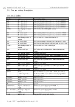
Page 13: ...ys on or off indicates abnormal device status DI1 DI1 input indicator light Green LED light on DI1 valid input off DI1 invalid input DI2 DI2 input indicator light Green LED light on DI2 valid input of...

Page 14: ...ator light Green LED light on DI7 valid input off DI7 invalid input DI8 DI8 input indicator light Green LED light on DI8 valid input off DI8 invalid input M31 XXAX0080G Symbol name Function Descriptio...

Page 15: ...ight on DO4 relay is closed off DO4 relay is off M31 AXXXA000G Symbol name Function Description PWR Power Indicator Red LED light on the system power supply is normal off the system power supply is ab...

Page 16: ...2 valid input off DI12 invalid input DI13 DI13 input indicator light Green LED light on DI13 valid input off DI13 invalid input DI14 DI14 input indicator light Green LED light on DI14 valid input off...

Page 17: ...DO5 DO5 output indicator light Green LED light on DO5 relay is closed off DO5 relay is open DO6 DO6 output indicator light Green LED light on DO6 relay is closed off DO6 relay is open DO7 DO7 output i...

Page 18: ...alid input DI5 DI5 input indicator light Green LED light on DI5 valid input off DI5 invalid input DI6 DI6 input indicator light Green LED light on DI6 valid input off DI6 invalid input DI7 DI7 input i...

Page 19: ...ion Description PWR Power Indicator Red LED light on the system power supply is normal off the system power supply is abnormal LINK Link indicator Yellow LED light on there is a link off no link flash...

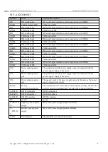
Page 20: ...t interface used in conjunction with COMC COMC DI switch input common terminal DI3 DI4 share the COMC common port DO1 DO1 switch output DO1 switching output interface used in conjunction with COM1 COM...

Page 21: ...terface used in conjunction with COM7 COM7 COM side of DI7 COM side of DI7 DI8 DI8 switch input DI8 switch input interface used in conjunction with COM8 COM8 COM side of DI8 COM side of DI8 VO Power o...

Page 22: ...ch output DO7 switching output interface used in conjunction with COM7 COM7 COM terminal of DO7 COM terminal of DO7 DO8 DO8 switch output DO8 switching output interface used in conjunction with COM8 C...

Page 23: ...ut interface used in conjunction with COM3 COM3 COM terminal of DO3 COM terminal of DO3 DO4 DO4 switch output DO4 switching output interface used in conjunction with COM4 COM4 COM terminal of DO4 COM...

Page 24: ...ed in conjunction with COMC DI10 DI10 switch input DI10 switch input interface used in conjunction with COMC DI11 DI11 switch input DI11 switching input interface used in conjunction with COMC DI12 DI...

Page 25: ...d in conjunction with COMC DO10 DO10 switch output DO10 switching output interface used in conjunction with COMC DO11 DO11 switch output DO11 switching output interface used in conjunction with COMC D...

Page 26: ...rface used in conjunction with COMC DO2 DO2 switch output DO2 switching output interface used in conjunction with COMC DO3 DO3 switch output DO3 switching output interface used in conjunction with COM...

Page 27: ...analog input interface used in conjunction with COM7 COM7 COM terminal of AI7 COM terminal of AI7 AI8 AI8 analog input AI8 analog input interface used in conjunction with COM8 COM8 AI8 COM terminal AI...

Page 28: ...set address The default device address is 1 hardware address 0 software address 1 device address 1 Device address setting range 1 255 Hardware address realized by DIP switch 4 bits DIP setting factory...

Page 29: ...down the host and the IO expansion module can be firmly connected together The specific operations are as follows First ensure that the host is not powered on and then connect the IO expansion module...

Page 30: ...t AI measurement current signal acquisition range 0 20mA or 4 20mA accuracy 3 resolution 12 bits Use single ended input sampling frequency 10Hz input impedance 100 Set the sampling range of all AI cha...

Page 31: ...ter is 0x0DA C the register type is a holding register and the function codes are 0x06 and 0x10 When writing the AI channel sampling range parameter if the written parameter value is not within the ra...

Page 32: ...ing quantity and use the IEE754 conversion tool to convert the hexadecimal data into a floating point number to obtain the input current The starting address of the AI engineering quantity integer val...

Page 33: ...lated parameters default to IPv4 related parameters 1 Working mode Switch the working mode of the module Server The device is equivalent to a server waiting for the user s client to connect The maximu...

Page 34: ...O expansion module zone 1 R 0x02 0 DI filter register name Register address Register type Data range description Related function codes Default state DI channel filter parameters 0x0DA3 holding regist...

Page 35: ...uA R 0x0 4 0 A I 5 IO expansion module 0x000 4 Zone 3 Project quantity 0 20000 represents 0 20ma 2 byte integer unit uA R 0x0 4 0 IO expansion module Zone 3 Project quantity 0 20000 represents 0 20ma...

Page 36: ...gister area Data range description Related function codes Default state AI1 sampling range Host 0x0DA C Zone 4 Valid values are 0 and 1 0 means 0 20mA 1 means 4 20mA R 0x03 W 0x06 0x10 0 AI2 sampling...

Page 37: ...03 W 0x06 0x10 DHCP 0X7533 Zone 4 1 0 off 1 on R 0x03 W 0x06 0x10 Device MAC address 0X7534 Zone 4 3 R 0x03 Local IP address 0X7537 Zone 4 2 R 0x03 W 0x06 0x10 subnet mask 0X7539 Zone 4 2 R 0x03 W 0x0...

Page 38: ...x06 0x10 Current negotiation status register 0X7586 Zone 4 1 Check whether the current negotiation is completed 0 The representative has not yet completed the negotiation 1 Representative negotiation...

Page 39: ...connection equipment 1 You can configure the device by selecting the interface serial port network port if you select the network port you must first select the network card and then search for the d...

Page 40: ...u Ebyte Electronic Technology Co Ltd Distributed IO Host M31 Series User Manual Copyright 2012 Chengdu Ebyte Electronic Technology Co Ltd 37 2 Select the corresponding device to operate the correspond...

Page 41: ...devices refer to Connection and Control 2 You can configure the basic parameters and network parameters of the device 3 After configuring the parameters click Save Parameters In the log output you wil...

Page 42: ...on Revision date Revision Notes Maintenance man 1 0 2023 9 27 initial version LT Contact Us Technical support support cdebyte com Documents and RF Setting download link www cdebyte com Thank you for u...

Reviews: