Chengdu Ebyte Electronic Technology Co.,Ltd.
【2DI + 2AI + 4DO】MA02-AACX2240 User Manual
Copyright ©2012–2021
,
Chengdu Ebyte Electronic Technology Co.,Ltd.
15
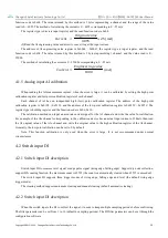
function code is 0x04. The value returned by this method is 2 bytes representing a channel, and the range of the value
read is 0
~
4095. The method of calculating the current is 0
~
4095 corresponding to 0
~
25mA.
The register type is discrete input register, and the read function code is 0x04.
������� =
�������� �����
4095
× 25 (��)
(2)Read the AI engineering value and directly convert to get the input current.
The address of AI engineering value register is 0x0064
~
0x0067, the register type is input register, and the read
function code is 0x04. The value returned by this method is 2 bytes representing 1 channel, and the value read is 0
~
25000.
The method of calculating the current is 0
~
25000 corresponding to 0
~
25mA.
������� =
����������� �����
1000
(��)
4.1.5 Analog input AI calibration
When reading the AI measurement current, when the error is large, it can be calibrated by setting the high point
calibration register and low point calibration register of each channel.
Each channel of AI has an independent high (low) point calibration register. The address of the high point
calibration register is 0x0190
~
0x0193, and the address of the low point calibration register is 0x0258
~
0x025C. The
register type is holding register, and the function code is 0x06, 0x10.
The calibration method can input an accurate current signal for the AI channel and write the value for calibration.
For example, if the AIx channel corresponding to the calibration device has an actual input current of 20mA, then read
the AI original value of the AIx channel and write the original value to the high calibration register of the AI channel.
Generally, the low point calibration can be set to 0 by default.
Note: This function calibration is only used when the error is large. It is not recommended under normal
circumstances.
4.2 Switch input DI
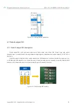
4.2.1 Switch input DI description
Switch input DI to measure level signal or edge pulse signal (rising edge, falling edge). Support dry node collection,
support DI counting function, the maximum count is 65535 (the count is automatically cleared when 65535 is exceeded).
The switch input DI supports three trigger modes of rising edge, falling edge and level (the default rising edge
trigger mode).
The clearing method supports automatic clearing and manual clearing (default automatic clearing).
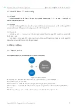
4.2.2 Switch input DI description
When the switch inputs the DI to collect the signal, it needs to keep multiple sampling periods before confirming.
The filter parameter can be set from 1 to 16 (default 6 sampling periods). The DI filter parameters can be set through the
configuration software


