background image

EC-520 User’s Manual 

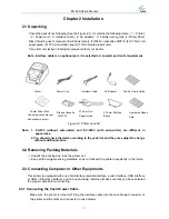
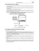
Cash Drawer Cable


Cash Drawer Connector 

Figure 2-2 Connecting the cash drawer cable 

Must use the cash drawer following the requirements noted on Table A-1 (Part 5.2) 

or the 

printer’s damage caused by this reason is out of maintenance service.   

2.

2.

3.2 Connecting the Parallel Interface Cable


1. Make sure that the host computer and the printer are both turned off, connect the parallel

interface cable to the connector of the printer, and tighten the screws as shown in


Figure 2-3.

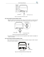
Parallel Interface 

Parallel Interface Cable 

Wire clip

Figure 2-3 Connecting the parallel interface cable

2. Connect the other end of the cable to the host computer’s parallel connector, and tighten the

two screws on both sides.

3.This printer’s parallel interface can be connected to network printing server. 

3.3 Connecting the USB Interface Cable


1. Plug the A side of USB interface (square type) into the printer’s USB interface connector.

2. Plug the B side of USB interface (flat type) into the computer’s USB interface connector.

- 4 - 

Summary of Contents for EC-520 Series

Page 1: ...User s Manual EC 520 Series Impact Receipt Printer...

Page 2: ...ase stop using and get a new one replaced Make sure the old one is far away from the printer so it can avoid someone who does not know the inside story getting damaged z Be sure to use the specified p...

Page 3: ...r Supply 6 2 5 Installing and Replacing the Ribbon Cassette 6 2 6 Installing the Driver 7 Chapter 3 Control Panel 9 3 1 Control Panel 9 3 1 1 Indicator LEDs 9 3 1 2 Function Keys 9 3 2 Printer Default...

Page 4: ...EC 520 User s Manual Appendix Commands List 35 iii...

Page 5: ...s have auto cutter 1 2 Application y Embedded installation and preprinting common bill printing market y Embedded installation and trilogy common bill printing market y Can be applied to tax controlle...

Page 6: ...ion Board Ribbon Cassette Ribbon Cassette Cover Ribbon Knob Roll Paper Cover Figure 1 2 Main parts of printer downwards without auto cutter Power Connector Cash Drawer Connector Interface Connector Pa...

Page 7: ...R113 Guarantee Repair Card Paper Guide ows driver Figure 2 1 Printer pack list Note 1 EC 520 without auto cutter and EC 520C with auto cutter are different in appearance 2 You should check the items a...

Page 8: ...cable to the connector of the printer and tighten the screws as shown in Figure 2 3 Parallel Interface Parallel Interface Cable Wire clip Figure 2 3 Connecting the parallel interface cable 2 Connect...

Page 9: ...screws as shown in Figure 2 5 2 Connect the other end of the cable to the host computer s serial connector and tighten the screws on both sides 3 5 Connecting the Ethernet Interface Cable Plug the RJ...

Page 10: ...ing the Ribbon Cassette 1 Make sure the printer is turned off 2 If you buy the printer without auto cutter EC 520 please open the ribbon cassette cover and then install the ribbon cassette directly If...

Page 11: ...steps to install a new ribbon cassette 3 Our company will not guarantee to keep the printer in good repair when it is damaged by using unauthorized ribbon cassette 2 6 Installing the Driver Install t...

Page 12: ...rinters click Have Disk click Next 5 Come out a window of Install From Disk Please according to the operating system environment you should select the path as follow CD ROM Driver WIN2000 XP vista tha...

Page 13: ...n turn on the printer at the same time Loosen the FEED key according to voice presentation times and the printer will perform the following functions correspondingly Voice presentation times Function...

Page 14: ...nterface 3 3 Explanation for Printer Setting Items 1 Through the inside setting of the printer EC 520 with Parallel Interface or USB Interface you can set the following items black mark setting print...

Page 15: ...g and Unidirectional printing Bidirectional printing is the factory setting Paper Width 76mm and 57 5mm 3 4 Self Test Function Self Test Mode While pressing the FEED key and holding on turn on the pri...

Page 16: ...nds three beeps and you should release the FEED key at the same time The printer will print the degree of column adjusting As shown in the following Figure Each press will add 1 to the original value...

Page 17: ...strictly according to instruction Hexadecimal Printing Mode While pressing the FEED key and holding on turn on the printer The printer sounds four beeps and you should release the FEED key at the same...

Page 18: ...oll Paper Guide 2 Take the paper roll into the paper filler Note the direction the paper pulled out of the roll as shown below Error Paper Roll Correct 3 Turn on the printer then hold both edges of th...

Page 19: ...ement of 1 144 inch Paper Feed Speed 140mm s Max Continuous paper feed Emulation ESC POS Interface types One cash drawer interface and one communication interface chose among parallel interface serial...

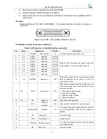
Page 20: ...e Print head life and MTBF above are realized by using appointed printing paper and ribbon cassette in the environment appointed by EC PRINTER 5 2 Interface 5 2 1 Cash Drawer Connector 1 The cash draw...

Page 21: ...9 27 DATA8 Date bit 8 IN OUT Means 8 bits of parallel data signal High level means logical 1 low level means logical 0 10 28 ACKNLG Answer out OUT Pulse width is about 12 sec Low level means that dat...

Page 22: ...by pair twist You must confirm that the interface cable is pair twist shielding line and every signal line is looped with ground line and pair twisted together Shielding line should be connected with...

Page 23: ...ctor is shown as Figure 5 6 Figure 5 6 pin s NO of the serial interface connector 2 Connecting figure of printer and computer with serial interface The figure is shown as follows DTR GND TXD RXD DSR 5...

Page 24: ...connector 5 3 Auto cutter Specification EC 520C is equipped with an auto cutter which parameter is shown as table A 4 Table A 4 Auto cutter Specification Item Specification Paper width 85mm max Paper...

Page 25: ...n the printer is used in dusty environment the carriage shaft may easily absorb dust which will affect the normal printing 2 Turn off the printer before cleaning 3 Print head becomes very hot during p...

Page 26: ...Phenomenon The printer can t print at all Solution 1 Check the ribbon cassette is installed correctly 2 Make sure that the interface cable is connected correctly Phenomenon The printed characters are...

Page 27: ...ribing the function and using instruction of this command 7 2 Explanation of Command HT Horizontal tab Format ASCII HT Decimal 9 Hex 09 Description Moves the print position to the next horizontal tab...

Page 28: ...command for character printing mode and is used for selecting size and underline of printed character The bit definition of print parameter n is shown as follows Value Bit Function 0 1 0 Character fo...

Page 29: ...e time until they are defined again or the printer is turned off The format of user defined characters is shown as follows b7 d1 d4 d2 d3 ESC Select bit image mode Format ASCII ESC m n1 n2 d n1 256 n2...

Page 30: ...kes the print head move to the standby position ESC n Cancel user defined characters Format ASCII ESC n Decimal 27 63 n Hex 1B 3F n Description Cancel he user defined character n This command function...

Page 31: ...lf dot distance Default value n1 n2 nK 10 All the horizontal tab positions ni should be within the line width allowed by the printer ni 1 80 it is equal to 40 7 7 or 7 9 dot matrix characters width or...

Page 32: ...print mode on or off n 0 255 only the lowest bit is valid When n 1 B unidirectional printing mode is set When n 0 B bidirectional printing mode is set Default n 0 ESC c 4 n Select paper sensor to sto...

Page 33: ...B 69 Description Execute a full cut of the paper roll by auto cutter ESC j Print and feed reversely Format ASCII ESC j n Decimal 27 106 n Hex 1B 6A n Description Print the data in the print buffer and...

Page 34: ...ows bit2 0 double height mode is disabled bit2 1 double height mode is enabled bit3 0 double width mode is disabled bit3 1 double width mode is enabled bit7 0 underline is disabled bit7 1 underline is...

Page 35: ...er Default n1 0 n2 2 FS W Turn quadruple size mode on off for Chinese character Format ASCII FS W n Decimal 28 87 n Hex 1C 57 n Description Turn quadruple size mode on or off for multi byte code chara...

Page 36: ...ng tearing cutting position offset from the black mark 3 Set the beginning print position offset from the cutter z m 0 or m 48 calculate the offset in the feed direction z nL nH The distance of offset...

Page 37: ...a of GS F command should be 2 Figure 7 5 Figure 7 4 3 When the tearing cutting position offset is not zero or the distance Q of the tearing cutting position offset from the beginning print position is...

Page 38: ...ng position n 1 144 inch and paper is cut partially only valid with auto cutter type But if the black mark is effective the value of n is ineffective The distance of paper feed is decided by the comma...

Page 39: ...E 1B 45 n Turn emphasized mode on off ESC G 1B 47 n Turn double strike mode on off ESC J 1B 4A n Print and feed paper ESC K 1B 4B n Print and reverse feed ESC U 1B 55 n Turn unidirectional printing m...

Page 40: ...L pH n m 1D 28 41 pL pH n m Test command GS F pL pH a m nL nH 1D 28 46 pL pH a m nL nH Set offset of black mark for printing and cutting position GS r 1D 72 n Transmit status GS V m n 1D 56 m n Select...

Reviews: