background image

7 Practical cases 

User Manual 


127 

Review the photographs to ensure that all the orientation points appear in all the 
photographs. 


 Click on "Next."   


We indicate that we have used the stereoTarget and we click on the icon to search all 

the images. 


Summary of Contents for eyesmap

Page 1: ...USER MANUAL EYESMAP Version 1 0 Revision A June 2015...

Page 2: ...Supply 15 3 5 Switching on the tablet 15 4 EyesMap Applications 17 4 1 Main Application Screen 18 4 2 Standard Windows and Buttons 19 4 3 Target Types and Their Use 20 5 EyesMap Modules 22 5 1 Menu 2...

Page 3: ...oto 78 5 5 1 Photo Development and Management Screen 78 5 5 2 Image Gallery 81 5 5 3 Image Viewer 81 5 5 4 Final Results Quality Selection Screen 82 5 5 5 Projection Plane Selection Screen 84 5 5 6 Sc...

Page 4: ...Create Mesh 112 6 2 3 Clean Noise 114 7 Practical Cases 116 7 1 Point to Point Photogrammetry 117 7 1 1 Methodology 117 7 1 2 Orientation with Targets 139 7 1 3 Use of Targets 146 7 2 3D Photomodelli...

Page 5: ...User Manual 5 1 Introduction In this chapter we shall see EyesMap Tablet How does Eyesmap work Eyesmap Standard Configuration 1...

Page 6: ...d in addition relies on other sensors to capture detailed 3D models of the environment and complex 3D geometric objects quickly and conveniently The results obtained by this tablet are 3D models of bo...

Page 7: ...ended This sensor is projector of infrared points combined with a CMOS sensor allowing to capture the environment in 3D in any light conditions The useful detection range of the depth sensor is up to...

Page 8: ...mes as standard in the following configuration 1 Transport Case 2 Tablet 3 AC charger and Cable Euro plug 4 GPS Antenna 5 Keyboard 6 Set of Targets existing of a 40 symmetric Point Targets b 20 Asymme...

Page 9: ...2 Technical Specifications In this chapter we shall see Tablet Cameras Depth Sensor GPS IMU 2...

Page 10: ...2 Technical Specifications User Manual 10 2 1 Tablet Find below the technical specifications of the main components of the Eyesmap Tablet...

Page 11: ...cision 1 5mm 1m 2 2mm 2m 30mm 3m Post processing 2 3mm 2m Maximum scanning range in motion Unlimited Maximum depth scanning distance 6 m Post processing time 3 min Depends on total scanning time and c...

Page 12: ...r Minimum Drift 1 9 mg Accelerometer Optimal Averaging Period 286 s Gyroscope Gyroscope Speed Max 2000 s Gyroscope Resolution 0 07 s Gyroscope White Noise 0 59 s Gryoscope Minimum Drift 0 0019 s Gyros...

Page 13: ...3 Starting up with EyesMap In this chapter you will find General Security Information Charging the battery Transport Power Supply Switching on the tablet 3...

Page 14: ...when following the operating instructions Do not expose the Tablet to extreme temperatures Do not use the Tablet near to artificial heating sources Do not use the Tablet in strong magnetic or electri...

Page 15: ...u are storing the tablet for a long period of time be sure NOT to leave the battery completely discharged Make sure the tablet is stored clean and in its original case Keep all components in a low hum...

Page 16: ...g Eyesmap Software Internet explorer Meshlab Daemon tools lite Microsoft Visual Studio 2008 2010 and 2012 NotePad Winrar Drivers of all the components installed Etc Once when switched on the Tablet yo...

Page 17: ...4 EyesMap Applications In this chapter we shall see Main Application Screen Text Windows and Standard Buttons Types of Targets and How to Use Them 4...

Page 18: ...ordinates distances and surfaces 3D Photomodelling this is the module used for creating 3D models with photogrammetric methods using the stereo cameras 3D Depth Sensor Generation of a 3D point cloud u...

Page 19: ...s and tools Click to minimise the application Click to close the application Before closing the application definitively you will be asked if you want to save the work you have done or if you wish to...

Page 20: ...ted by the system automatically in the images taken The targets identified provide information for the orientation of images measuring of points or scaling of 3D models depending on the case stereoTar...

Page 21: ...y for small objects While it is not necessary for the stereo target to appear in all photographs it is recommendable for it to appear in as many images as possible so that scaling is more accurate Asy...

Page 22: ...y Image Selection Screens o Results Screen Depth Sensor o RGBD Menu o Capture a 3D Model o Post Processing o 3D Viewer Orthophoto o Photo Development and Management Screen o Final Results Quality Sele...

Page 23: ...Application Screen The four management options are found on the main screen of the module By clicking on any of the four options you can access the corresponding actions related with each one 5 1 2 Pr...

Page 24: ...select the project management option the application shows the main screen where the three available actions appear create a new project load an existing project and save the current project New Proj...

Page 25: ...urs depending on the type of project in question If the current project is a temporary project the application has been started and the project has not been saved with any name this option will save t...

Page 26: ...e temporary project that you were working on When the application opens again the temporary project recuperation screen will appear in which it will be possible to recuperate the project that you were...

Page 27: ...you if you want to save the temporary project or not Likewise if you have been working on a loaded project the application will inform you that the changes have been saved automatically allowing the u...

Page 28: ...carried out a Calibrations directory has been created at C EyesMapProject AutoCalibration All EyesMap devices have a default calibration configuration obtained in an optimal way and called calDefault...

Page 29: ...rientation of a pair and it represents the angular position and orientation associated with the pair of images The orientation defined here shall only be used if to take measurements with EyesMap only...

Page 30: ...entation of cameras and load orientation Orientation Click to set camera orientation To complete this action consult support ecapture es Load Orientation Click to load one of the orientation configura...

Page 31: ...the software you must have an internet connection Once the module has detected the software version installed on the device it will tell you if it is necessary or not to update with the message new s...

Page 32: ...ain using the captured images three dimensional coordinates distances and surfaces formed by different points For the purpose of simplicity and clarity the main menu of this module has been broken dow...

Page 33: ...amera Take all the shots with a single camera Stereo Camera Click if you wish to activate both cameras Load Images Click if you wish to load previously captured images If you choose the option to acti...

Page 34: ...photogrammetry for example areas with a very homogeneous texture like walls painted a single colour plastic or glass objects or water are not good for photogrammetry as the system has trouble finding...

Page 35: ...find the following buttons Take Photographs Click to take photographs Load Images Click to load existing images The images must have been captured with the EyesMap cameras Discard Images Select the ph...

Page 36: ...select or de select one or several images you only have to click once on them The selected images stand out from the rest because a black frame appears around them 5 2 3 Image Viewer To see the larger...

Page 37: ...ically by matching of the homologous points found Of the three types of orientation this one is the most automatic and the quickest It can be used in practically all circumstances provided that the ob...

Page 38: ...and 2 3 there are at least 9 points in common Areas not in common can have fewer points if desired in order to complete orientation on all parts of the image This orientation method has the drawback...

Page 39: ...th priority over the stereoTarget scaling Looking for homologous points in all images Automatic search for homologous points This option is selected by default and it searches for the orientation poin...

Page 40: ...en in the previous graphic between images 1 2 and 2 3 there are at least 9 symmetrical targets in common 5 2 4 3 1 Methodology for Orientation with Targets To carry out orientation with targets it is...

Page 41: ...ree dimensional coordinates of the symmetrical targets centre points 5 2 5 Scaling with the StereoTarget On this screen you must specify if you wish to use the stereoTarget to scale the results or not...

Page 42: ...l images selected by default or choose the images in which the stereoTarget should be looked for If the stereoTarget appears in all images select the first option Otherwise select the second option an...

Page 43: ...s automatically recognised a cross appears in the centre of each target which makes it up When performing manual selection it is recommendable to mark one of the corners in one of the squares and the...

Page 44: ...s is displayed in the centre of the detected target Remember that you can also do scaling with the Scale tool The tools available in this screen are the following Coordinate Measurement Select this if...

Page 45: ...dentifier pX with X being the point number distances are given the identifier dX and surfaces are assigned the identifier sX You may include your own identifier or code for each coordinate distance or...

Page 46: ...B Selection Tool To delete an element it must first be selected Choose this tool to select the area where the elements which you wish to delete are located and drag your finger over the screen to draw...

Page 47: ...with a real distance which is known you can use the Scale tool You should input the real measurement of the distance and then select the two points which make up the distance This tool is treated wit...

Page 48: ...document Export Tool Click to export the results to other formats TXT TXT 3D JPG DXF In the export window you must choose the file format its name and the directory where you wish to save it The chara...

Page 49: ...he results in DXF format so that they can be viewed and edited in different external pieces of software Coordinates shall be saved in the DXF file as points distances as lines and surfaces as a set of...

Page 50: ...clouds to be scaled you should use the stereoTarget the small one for small objects the big one for medium and large objects 5 3 1 Photograph Capture and Management After selecting the 3D Photomodell...

Page 51: ...verlapping can get to be almost 100 it would be better for improved orientation Not all objects are good for photogrammetry for example areas with a very homogeneous texture like walls painted a singl...

Page 52: ...be significant differences between the two cameras In the photograph capture and management window you will find the following buttons Take Photographs Click to take photographs Load Images Click to...

Page 53: ...select or de select one or several images you only have to click once on them The selected images stand out from the rest because a black frame appears around them 5 3 3 Image Viewer To see the larger...

Page 54: ...vanced parameters by default for you Higher model quality means more points will be included in the point cloud and in general the 3D model will be more detailed On the downside a higher number of poi...

Page 55: ...odel Point Density The higher the point density you select high medium or low the more points the 3D point cloud generated will have Keep in mind that a higher point density does not imply better resu...

Page 56: ...sh to scale with the stereoTarget Two new groups of options will appear Type of stereoTarget used large selected by default or small Search in all images selected by default or choose the images in wh...

Page 57: ...Master Image Everything appearing in the image designated as master shall be modelled in the resulting point cloud Secondary Images Images which are assigned to the master image and which help to comp...

Page 58: ...to model remember you do not have to model the entire master image if you do not wish to do so 4 Repeat the process to choose master images if you wish to select more or if you only need one master i...

Page 59: ...ge marked in blue Select the images that you wish to set as secondary If you have selected the wrong image just click on it again and it will automatically de select It is recommendable to assign one...

Page 60: ...ules User Manual 60 Step 3 Paint a mask over the master image Draw Sky Click to paint part of the sky in the image It is not necessary for you to paint the entire sky Everything will be modelled excep...

Page 61: ...the part of the image that you wish to model Select in white everything you wish to be modelled in the master image Draw All Select this to model all the parts of the master image Type of Brush Selec...

Page 62: ...Click to erase everything you have painted selected on the image Use this button if you have made a mistake or if you wish to improve your selection Step 4 Repeat the process to choose more master ima...

Page 63: ...selected images from the list If you select a master image and delete it your secondary images and your masks will also be deleted automatically If you select a secondary image and delete it the assoc...

Page 64: ...cally go to the folder or keep working and visualise the results when you wish Example If you have selected more than one master image and have input the name example the names of the point clouds wil...

Page 65: ...r This provides an advantage over photogrammetry as it can capture homogeneous areas and areas with little texture On the other hand the accuracy of the point cloud generated is less with accuracies o...

Page 66: ...l the actions carried out with the depth sensor in the current project 5 4 2 Capture a 3D Model When you click on the Capture button the vSLAM RGBD RealTime application opens This application captures...

Page 67: ...unknown scene based upon the visual information the camera captures To accomplish this tracking of a set of visual features generally characteristic points is carried out in the succession of images c...

Page 68: ...be post processed later is automatically saved Do not do the capture at a high speed let EyesMap compute the key frames to properly orient itself The data which is automatically saved and which can be...

Page 69: ...es in the same place where the process started This button does not do any additional processing it will only help you to take the sequence of shots correctly and improve post processing results Delet...

Page 70: ...key frame is going to be generated as there is new information in the capture being undertaken MOVE Informational message which tells the user that he she has not yet moved enough to generate a new ke...

Page 71: ...with the continuing of the capture a window appears with the image of the last key frame captured Try to make the real time camera image line up with the image of the last correct key frame in order...

Page 72: ...divided into 3 parts Application status bar This allows you to minimise restore and close the application Point cloud viewer This shows the 3D model which is being post processed Information box this...

Page 73: ...time Open Sequence When you click on this button the following dialogue box opens Select the saved sequence that you wish to post process In the event that the selected directory is incorrect or does...

Page 74: ...post processing is being carried out so that execution errors do not arise Notice that the information box shows the number of post processed key frames which have been analysed and those which remain...

Page 75: ...process will also take more time Save Press this button to save the post processed key frames The following files are generated k0 ply to k7 ply contain each one of the correctly oriented key frames...

Page 76: ...l of sampling dictates the level of data processing included in post processing The lower this number is the greater capacity for improvement post processing will have but it will take more time This...

Page 77: ...5 EyesMap Modules User Manual 77 5 4 4 3D Viewer Click to open and view a 3D model created with the depth sensor...

Page 78: ...ave been corrected to create an orthogonal projection without the effects of perspective Therefore it is possible to use said orthophoto to take exact measurements unlike a simple photograph which wil...

Page 79: ...photogrammetry for example areas with a very homogeneous texture like walls painted a single colour plastic or glass objects or water are not good for photogrammetry as the system has trouble finding...

Page 80: ...find the following buttons Take Photographs Click to take photographs Load Images Click to load existing images The images must have been captured with the EyesMap cameras Discard Images Select the ph...

Page 81: ...select or de select one or several images you only have to click once on them The selected images stand out from the rest because a black frame appears around them 5 5 3 Image Viewer To see the larger...

Page 82: ...uality Selection Screen Screen which allows you to choose the quality of the final orthophoto This will directly influence results Option 1 Take the orthophoto in high resolution Recommended for less...

Page 83: ...ith correct parameter selection Advanced Options Click to modify the resolution parameters If this is not clicked the model will be high resolution Change the point density for the final model The hig...

Page 84: ...ine it follow the following steps Select the image to define the projection plan clicking on the desired image The image will turn green If you selected the wrong image just click the desired image an...

Page 85: ...orthophoto may not be correctly generated Choose the type of brush square or round Brush thickness move the sliding bar towards the left or right for greater less brush thickness Restore Click to eras...

Page 86: ...d X axis reference points Control Points These are the 3D points which assist the system in the generation of orthophotos It is important to define plenty of control points being distributed throughou...

Page 87: ...the points on the image chosen and or on the two adjacent images left and right For a point to be confirmed it must appear in at least two of the three images At minimum 4 control points should be sel...

Page 88: ...rm it You can select reference points on the X axis in different images Confirm Click to confirm an orientation point which has been selected Discard Image This is useful when you confirm a point on o...

Page 89: ...Choose this tool to select the area where the elements which you wish to delete are located and drag your finger over the screen to draw the desired area The elements which are inside the selected ar...

Page 90: ...ry recommendable to do so choose more points on other images You will return to screen 3 6 6 for choosing control points and reference points on the X Axis for the other selected images If you do not...

Page 91: ...oughout the scene to be processed and or paint the projection plane correctly 5 5 9 2 Orientation Errors During data processing orientation of images is calculated in situ If a problem occurs an orien...

Page 92: ...we are only going to explain two protocols in detail as these are enough for the user to take real time measurements and obtain RINEX data for post processing NMEA Captures data only in real time o It...

Page 93: ...protocol To change the protocol type see section 5 6 4 Change Protocol 5 6 2 COM Port Properties and Changing COM Port 5 6 2 1 Properties In this section we will explain the communication properties...

Page 94: ...s GPS GNSS Port Settings Port Check that the COM port is correct see section 5 6 2 2 COM Port Baud rate You should always choose 115200 Protocol NMEA see section 5 6 1 Protocols and section 5 6 4 Chan...

Page 95: ...s on the device Generally the correct port number for your device will come pre assigned If there is a problem with the COM port check to ensure that the port number is correct To check if the port nu...

Page 96: ...3 Real Time Data Screen Below a description of the steps necessary to take a measurement and view the data in real time is set forth Click to begin to view data on the screen in real time Remember tha...

Page 97: ...ck to stop seeing real time coordinates Data will also stop being stored and it will be saved in the file set for these purposes 5 6 3 1 Error COM port is busy or nor available Check that the COM port...

Page 98: ...in with this protocol 5 6 4 Change Protocol Use or change protocols in the event of the error No connection to receiver or if you want to create a binary file this type of file is necessary for conver...

Page 99: ...5 EyesMap Modules User Manual 99 3 Choose option 3 BINR 4 Click on Apply Settings to apply the protocol change 5 Click OK The protocol is now changed...

Page 100: ...ol If you want to gather data in real time again you have to have the NMEA Protocol activated therefore it is probable that you ll have to change from the BINR Protocol to the NMEA Protocol if this is...

Page 101: ...5 EyesMap Modules User Manual 101 2 Change the baud rate to 115200 3 Change the protocol to 2 NMEA 5 Click OK 4 Click on Apply Settings to apply the protocol change...

Page 102: ...ith an external post processing software package for GPS data or with other RINEX data from reference stations in your area in order to improve the accuracy of the position Post Processing Click here...

Page 103: ...ile To be able to use this module first you must change the protocol type to BINR see section 5 6 4 To save the file use the first section of the interface Incoming data source Choose the correct COM...

Page 104: ...l 104 Check that this corresponds with your options Click to choose a file path for the data to be saved to Choose a folder and input the file name in the File Name field Choose binary RINEX file Clic...

Page 105: ...art A file of 10 15 minutes in length is recommended for better precision The file is being saved Wait for about 1 minute and check that all the information is OK If it is not Ensure that you have a G...

Page 106: ...o carry out post processing with external software packages and improve accuracy To convert files to RINEX use the second part of the interface 5 6 5 2 1 To carry out direct conversion to RINEX of the...

Page 107: ...al 107 5 6 5 2 2 To carry out conversion to RINEX of a previously saved file Choose the data source From File Click to open the binary file which was previously saved Click on Start Continue with the...

Page 108: ...6 Viewers In this chapter we shall see MeshLab Touch Filters o Remove Outliers o Create Mesh o Clean Noise 6...

Page 109: ...either If your editing needs are more than what is offered by this software package we recommend you install professional editing software on your PC List of free viewers MeshLab http meshlab sourcefo...

Page 110: ...elling module and depth sensor is a aln file This file is a project with the MeshLab format which will allow you to open with just a click the files which contain the point clouds generated in a proce...

Page 111: ...nt 6 2 Filters This Touch version of MeshLab introduces 3 filters 6 2 1 Remove Outliers With this filter you can delete outlier points to soften the noise in the point cloud An example is shown below...

Page 112: ...this filter is selected the following popup configuration window appears Normals Field Calculates the normals of the point cloud depending on the neighbours A high value for this parameter improves re...

Page 113: ...noise small values are recommended 6 for both fields To apply this filter to an entire project aln the option Compute All Files must be marked otherwise only the selected model will be filtered Obser...

Page 114: ...ide fields These two fields are recommended to be set high in the event that the point cloud which is going to be filtered is relatively clean values between 10 and 12 are recommended for both fields...

Page 115: ...6 Viewers User Manual 115 If you have questions about the workings of other tools in MeshLab Touch check the following document http www cyi ac cy system files MeshLab 20Documentation1 pdf...

Page 116: ...7 Practical Cases In this chapter we shall see Point to Point Photogrammetry o Methodology o Orientation with Targets o Use of Targets 3D Photomodelling Depth Sensor Orthophoto GPS 7...

Page 117: ...s with EyesMap Accuracy is related to the number of photographs taken of the object the angle of convergence and the quality of the images Accuracies One shot 0 9 mm 4 m depends on the number of image...

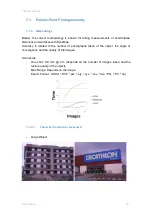
Page 118: ...7 Practical cases User Manual 118 Medium Object...

Page 119: ...7 Practical cases User Manual 119 Small Object...

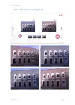
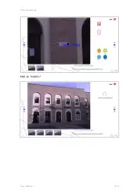
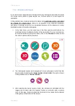
Page 120: ...7 Practical cases User Manual 120 7 1 1 2 Photo Development and Management...

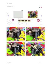
Page 121: ...7 Practical cases User Manual 121 Small Objects...

Page 122: ...ographs of the object following the recommended graphic for photogrammetry Photo shots are taken in situ with the capture button Four pairs are taken and in this case the left images are deleted to tr...

Page 123: ...User Manual 123 The photographs are observed one by one to be sure that they are well centred around the object to be measured to ensure they are clear and to make sure that none of them needs deleti...

Page 124: ...ntation homogeneous textures or colours automatic orientation may generate errors which affect the measurements To avoid this type of errors in areas where textures are unfavourable manual orientation...

Page 125: ...ck on confirm and the orientation point is recorded Repeat the process for at least 8 more points a minimum of 9 orientation points in total The application will not allow you to continue if you have...

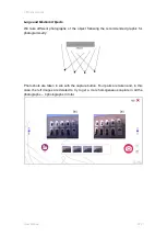
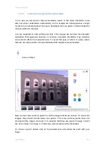
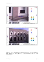
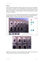
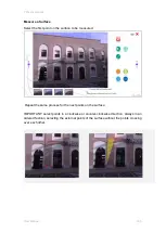
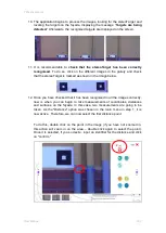
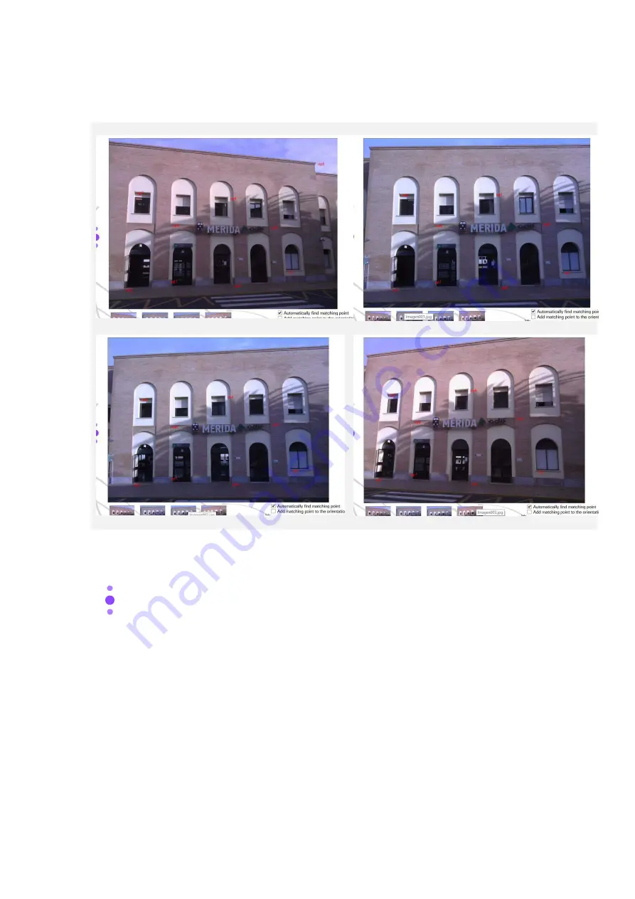
Page 126: ...7 Practical cases User Manual 126 9 Orientation Points...

Page 127: ...er Manual 127 Review the photographs to ensure that all the orientation points appear in all the photographs Click on Next We indicate that we have used the stereoTarget and we click on the icon to se...

Page 128: ...for in all the photographs Click on Next If the stereoTarget is not found automatically it can be found manually by selecting it with the stereoTarget point button activated the two upper right corne...

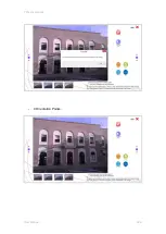
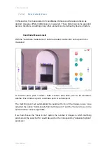
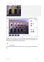
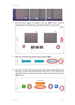
Page 129: ...7 Practical cases User Manual 129 Click on Confirm...

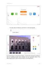
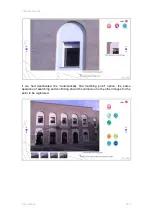
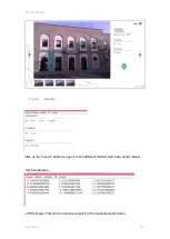
Page 130: ...7 Practical cases User Manual 130 The distance of the stereoTarget will be saved Click on Next...

Page 131: ...utton activated double click on the point to be measured To add the point push confirm Push confirm after each point to be measured whether it be a distance point coordinate point or surface point The...

Page 132: ...l cases User Manual 132 If we had deactivated the Automatically find matching point option the same operation of searching and confirming should be carried out in the other images for the point to be...

Page 133: ...shown on all images It is recommendable to check that said distance is correctly configured on all images If there is an error due to a mistaken point being marked the incorrect distance should be sel...

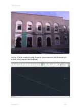
Page 134: ...7 Practical cases User Manual 134...

Page 135: ...n the surface to be measured Repeat the same process for the next points on the surface IMPORTANT select points in a clockwise or counter clockwise direction always in an ordered fashion selecting the...

Page 136: ...yesMap can do more than one coordinate distance and surface measurement on the same screen To accomplish this the user just has to click the icon for the object to be measured and repeat the aforement...

Page 137: ...ical cases User Manual 137 7 1 1 5 Results Click on the export button to export to the different formats which are shown below 3D Coordinates JPEG Image This can be used as a sketch of the measurement...

Page 138: ...7 Practical cases User Manual 138 DXF file This file is useful for using the points lines and areas in CAD formats as can be seen in the following image AutoCAD...

Page 139: ...graph 1 In the main menu you can select any of the three point to point buttons the coordinate button the distance button or the area button For your convenience as measurements are going to be taken...

Page 140: ...mber that you can pinch the screen to zoom and double click to adjust the zoom back to the original size You also have touch activated sliding movements to navigate between the images as shown in the...

Page 141: ...tre right portion of the screen 8 Select the orientation with targets option and click Next 9 As we wish to scale with the stereoTarget and the stereoTarget appears in all the images on the stereoTarg...

Page 142: ...as shown in the image below 12 Once you have checked that it has been recognised in all the images correctly now is when you can begin to take measurements of coordinates distances and surfaces on the...

Page 143: ...ou a thumbnail of the point that was selected in the first image To mark the second distance point follow the same procedure omitting the creation of an identifier which you already did in the first p...

Page 144: ...surfaces in this case none To save the results click on the Export button 14 When you click on the Export button the data export window will open in which you can choose to export the data as a TXT Da...

Page 145: ...r Manual 145 c JPG Image jpg This exports in JPG format the image displayed on the screen d DXF CAD dxf This exports the results in DXF format so that they can be viewed and edited in different extern...

Page 146: ...can select any of the three point to point buttons the coordinate button the distance button or the area button For your convenience as measurements are going to be taken click on the Distance button...

Page 147: ...ts automatically Likewise this is a heterogeneous image therefore we will use automatic orientation Select the automatic orientation option and click on the Next button 5 As we wish to scale with ster...

Page 148: ...pear and the message Targets are being detected is displayed 8 Once the search has completed the targets detected appear marked as points p0 p1 pN and the target detection tool is hidden Both before a...

Page 149: ...s obtained for the coordinates including those corresponding to detected targets distances and surfaces To save the results click on the Export button select the DXF format the file path where you wis...

Page 150: ...rom EyesMap coordinates are saved as points distances are saved as lines and surfaces are saved as sets of continuous lines not polylines In this case there were 8 targets Therefore the resulting DXF...

Page 151: ...ended to have 100 overlap The texture of the object to be modelled should be heterogeneous and objects with homogeneous textures plastics water or glass should be avoided as these elements make it dif...

Page 152: ...be sure that the photos are clear and that the object to be modelled is centred Click on Next Final Model Resolution Screen Option 1 High Medium Low On this screen we have two options to set the quic...

Page 153: ...ases User Manual 153 Click on Next stereoTarget Scaling Screen In this case the stereoTarget has not been used Had the stereoTarget been used we would have used the large stereoTarget for medium and l...

Page 154: ...een A master image has been chosen as can be seen below In said master image everything we wish to model has been included Two secondary images have been assigned to this master image In the secondary...

Page 155: ...cases User Manual 155 Once the secondary images have been chosen we click on confirm The next step is to paint with the round brush all the parts of the object that appears in the photo and which we w...

Page 156: ...h has been painted is displayed Therefore in the final 3D model only that part of the Alcazaba will be modelled For more information on master images secondary images and masks consult the photomodell...

Page 157: ...7 Practical cases User Manual 157 We choose a second master image undertaking the same process for this image as with the first one we chose Two secondary images are assigned and confirm is clicked...

Page 158: ...h we wish to model has been drawn with the brush In the top image we can see the image taken and in the bottom the mask which has been painted is displayed Just like in the first master image the same...

Page 159: ...to the master and secondary image selection screen For this case more images are not necessary But if we had more photographs more master images would probably be necessary Click on Next After proces...

Page 160: ...where the 3D model is found opens There is a PLY file for each master chosen in this case two But if the file alcazaba_Merge aln is clicked on all the PLY files created will open Here the final 3D res...

Page 161: ...M all of said point clouds will be aligned on one sole coordinate system 15 In the main menu select the 3D Depth Sensor button marked with a black circle in the image below 16 The menu with the 4 opti...

Page 162: ...apture and push the Start button Be sure that the area where you have started to capture has enough characteristic points as this will improve final results Now move around the room slowly while the d...

Page 163: ...ted here that due to processing constraints a sole depth sensor capture can have up to 400 key frames at maximum IMPORTANT Worse results are obtained if you pass over an area you have already captured...

Page 164: ...re the data has been saved is sequence_1724 The contents of the directory for the real time shots is as follows Do not delete or modify these files and directories which have been automatically genera...

Page 165: ...7 Practical cases User Manual 165 19 The post processing programme opens Click on the Last button which will automatically load the last capture taken in real time...

Page 166: ...This process can take several minutes depending on the number of key frames and their nature When the 59 keyframes are calculated the process finalises and the options become available again Review th...

Page 167: ...ontain the following files The file samply ply contains a sub sample of the 3D model generated The text files cameraTrayectoryOpt txt and cameraTrayectoryRaw txt contain the relative position of each...

Page 168: ...ount Take clear photos try not to move while you are capturing Avoid the sun facing you Capture the entire object to be measured try to place said object in the centre of the image Take different shot...

Page 169: ...the capture button The desired images are taken In this case a total of 66 photographs have been taken Photograph Capture Below the first 8 images which will be used to create the orthophoto in this e...

Page 170: ...sure that none of them needs deleting Click on Next 7 4 1 2 Model Resolution Quality The next step that you should undertake to create an orthophoto of the scene object selected is to indicate the qua...

Page 171: ...options In this practical case the advanced options will be used Manually choose the different parameters which will dictate the processing time and the quality of the final model Below the advanced o...

Page 172: ...e to create an orthophoto left to right or vice versa up to down or vice versa Number of images per group 3 Groups of 3 4 images are recommended when repetitive scenes are photographed in the example...

Page 173: ...ane we wish to use to ortho project the orthophoto To do so the plane should be selected as follows Select the image onto which you wish to set the projection plane and click on Next In the next image...

Page 174: ...ths are similar you can select them as a single plane as shown in the following example Selected Projection Plane Painted in white 7 4 1 4 Select Control Points and Reference Points on the X Axis The...

Page 175: ...Manual 175 The selected image and the two adjacent images will load so that points can be selected on them In total 4 control points have been assigned green and 1 one reference point on the X axis re...

Page 176: ...come back up to assign more control points and reference points on the X axis You should select control points on the images as you wish until at minimum there are 4 control points selected and 2 X a...

Page 177: ...ber of points you have selected is indicated in the information box found in the lower part of the screen The minimum number of points has not been fulfilled another image is selected to choose more c...

Page 178: ...u select the greatest number of control points possible Said points should also be distributed throughout the entire scene In this way results will be better Once confirmed click on Next again The pro...

Page 179: ...ess the images to create the orthophoto Please wait until the process is complete The result is a grayscale image which arises from merging the images into one single image In this step you must choos...

Page 180: ...orthophoto Note it is not necessary to select everything only what you want to obtain The final result is the desired orthophoto Input a name in the field Orthophoto Name to save your work Once a name...

Page 181: ...and over different images Try to make your images as perpendicular as possible to the scene which you wish to create and be mindful of having enough overlap between images 7 5 GPS This practical case...

Page 182: ...her data is to check that the port configuration parameters are correct by clicking on the Settings button To accomplish this we check the port number the baud rate and ensure that the protocol type i...

Page 183: ...to start to view data in real time and to be able to change the protocol type from NMEA to BINR this is necessary to create a file which can be converted to RINEX As can be seen in the image in the m...

Page 184: ...ype is changed from NMEA to BINR To do this we click on the Serial Port Settings PORZA button which is highlighted in the following image We change the port parameters in the right hand side of the in...

Page 185: ...ady receiving data in the BINR protocol These steps although we started working in real time and our objective is to obtain a valid file for post processing are completely necessary as we are preparin...

Page 186: ...rface From this interface we will be able to save a file of binary observations for subsequent conversion to RINEX files The first step is to choose the correct COM port see section 5 6 2 2 on the GPS...

Page 187: ...tton and next a new window opens where we can choose the folder where we want to save the file we are going to create In the File Name box we input the file name In this case it is P1 We click on Open...

Page 188: ...a In the image below we see that the duration of observation was 15 minutes and 5 seconds We remind you that best results are obtained with between 10 and 15 minutes of observation We click on stop an...

Page 189: ...ccomplish this in the conversion part of the interface we click on the button to open a folder and select the folder where we want to save the RINEX files that will be generated In this case we have s...

Page 190: ...ervation file P1 to the RINEX format We open the GPS folder and find inside the RINEX files generated In order to improve accuracy these RINEX files generated from the P1 file can be opened with an ex...

Page 191: ...7 Practical cases User Manual 191...

Page 192: ...ror These types of errors are associated with the point to point photogrammetry module the orthophoto module and the 3D Photomodelling module Because of the characteristics inherent to the depth senso...

Page 193: ...own when for one or several non consecutive images enough common points are not found to carry out orientation EyesMap will delete these images from the 3D reconstruction process Warning Modules Orien...

Page 194: ...you take the photos with more overlap be sure they are well focused and don t stand too far away Error Modules Error Please not enough images Point to Point Orthophoto 3D Photomodelling This error can...

Page 195: ...ection Plane was drawn incorrectly Orthophoto This error may be due to the lack of control points in the orthophoto you should add more or you may not have drawn the projection plane correctly it coul...

Reviews: