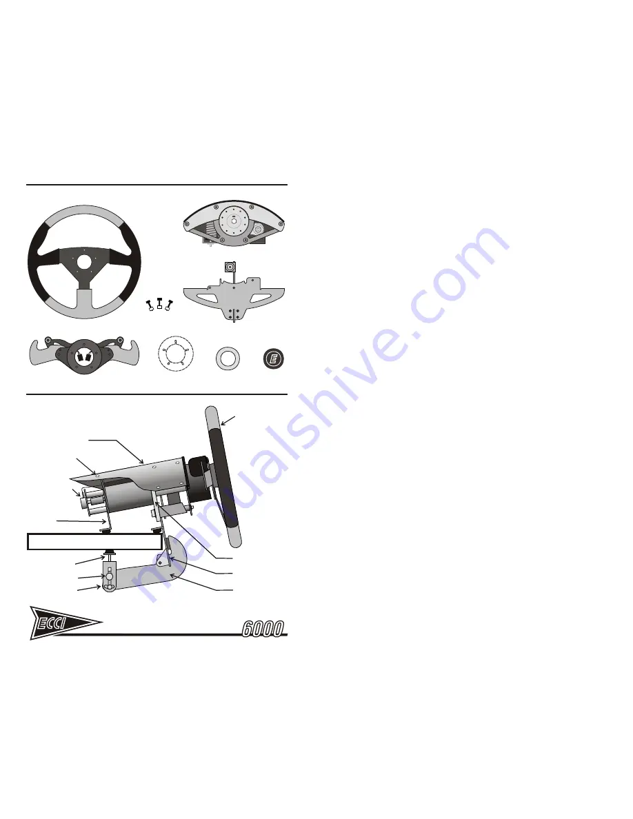
STEERING WHEEL
TRACKSTAR
SHIFT PADDLE SET
BUTTON
CENTER
RETAINING RING
BUTTON
Figure 1 - WHEEL UNIT COMPONENTS
STEERING UNIT CHASSIS
TABLE MOUNTING BRACKET
Figure 2 - WHEEL UNIT ASSEMBLY
STEERING WHEEL
TABLE MOUNTING
BRACKET
CENTRAL CHASSIS
STRUCTURAL PLATE
BRACKET
TENSIONING BOLT
TENSIONING PIVOT
TABLE MOUNTING
ARM
PIVOT SET SCREW
WHEEL UNIT HOUSING
POTENTIOMETER
HOUSING SCREWS
REAR LEG
TABLE BRACKET
SCREWS & NUTS
WHEEL SPACER
(OPTIONAL)
1.0
WHEEL UNIT SETUP AND ADJUSTMENT
1.1
UNPACKING THE WHEEL UNIT
Before unpacking and setting up your driving system, prepare a clean area with
adequate room for laying out the components. Review the list of wheel unit parts
[Figure 1] and verify that everything is present to complete assembly.
ECCI recommends keeping the original box and packing materials in case the
unit needs to be shipped in the future. If shipping is needed, the unit MUST be
shipped partially disassembled as originally received, or damage will result.
1.2
WHEEL MOUNTING BRACKET
Before starting, examine Figure 2 for how the wheel unit should appear when
assembled. In a sufficient workspace lay out the mounting bracket assembly,
steering wheel, shift paddle set, center logo button, and button retaining ring.
1. Set the main steering chassis on a table upside down on a terry cloth towel
or other soft non-abrasive cushioning material to avoid scratching the cover.
2. Using a 3/16 inch hex wrench, loosen the two center-most chassis tube bolts
[Figure 3]. Do not remove them; back them out until the nuts between the
bolt tubes and the gray central structural plate can be removed and
discarded. Then re-install the two bolts about one turn and leave them loose.
3. Invert the table bracket assembly towards the central chassis structural plate
and align the two central slots with the previously loosened chassis-tube
bolts [Figure 3]. The table bracket should be seated between the spacer
tubes and the gray central chassis structural plate.
4. Using a 1/8 inch hex wrench, attach the mounting bracket with the 3
supplied bracket mount screws and nuts [Figure 3]. After tightening these
screws, turn the two center-most chassis bolts until tight, fully securing the
mounting bracket to the central chassis structural plate.
5. Turn the unit upright and secure to a tabletop edge using the clamp of the
mounting bracket [Figure 4]. Rotate the bracket tensioning bolt [Figure 2]
until it is perpendicular to the underside of your mounting surface. Turn until
it contacts the underside of the surface. Do not over tighten. Turn till finger-
tight and then using a wrench, turn one-half turn more. Then lock the bracket
by tightening the pivot set screw.
1.3
STEERING WHEEL ASSEMBLY
1. With the wheel unit upright and secured to the tabletop the steering wheel
and shift paddles can be mounted. Prior to assembly inspect the shift paddle
set [Figure 5]. Note the importance of the two wire management slots at the
back side of the paddles. These slots accommodate the button wiring when
the paddle/wheel assembly is tightened down to the steering unit hub. It is
critical that the wires pass through these slots and avoid getting pinched
during assembly.
Remove the five wheel attachment screws from the paddle set. Discard
the small nuts that held them at the back of the assembly. From front to
back, the screws will pass through the steering wheel, optional wheel
spacer (if supplied), the shift paddle assembly, and into the threaded
holes in the hub


