Pipe Mounting:
The 6500 series base comes with 1” NPT threads for
pipe mounting.
Temporary Mounting, Vacuum-Magnet Mount:
The Vacuum-Magnet Mount
feature includes a suction cup on the bottom of the beacon, with a magnet inside
of the suction cup, for a secure, temporary mount. The beacon should be placed
in the center of the roof where the least amount of curvature occurs. Before
installing, make sure the mounting surface is clean and there is no debris on the
bottom of the beacon or on the roof of the vehicle, which could reduce the holding
power of the suction cup and magnet. Place and remove the beacon without
sliding to avoid scratching the paint on the vehicle. After placement, the beacon
should adhere firmly to the surface. If the unit slides or moves easily, a proper
installation has not been obtained. To release the vacuum, lift the tab to release
the airlock (see Figure 2). To protect the Vacuum-Magnet Mount assembly, return
beacon to the box when not in use.
Do not attempt to attach the beacon to an
ice-covered surface.
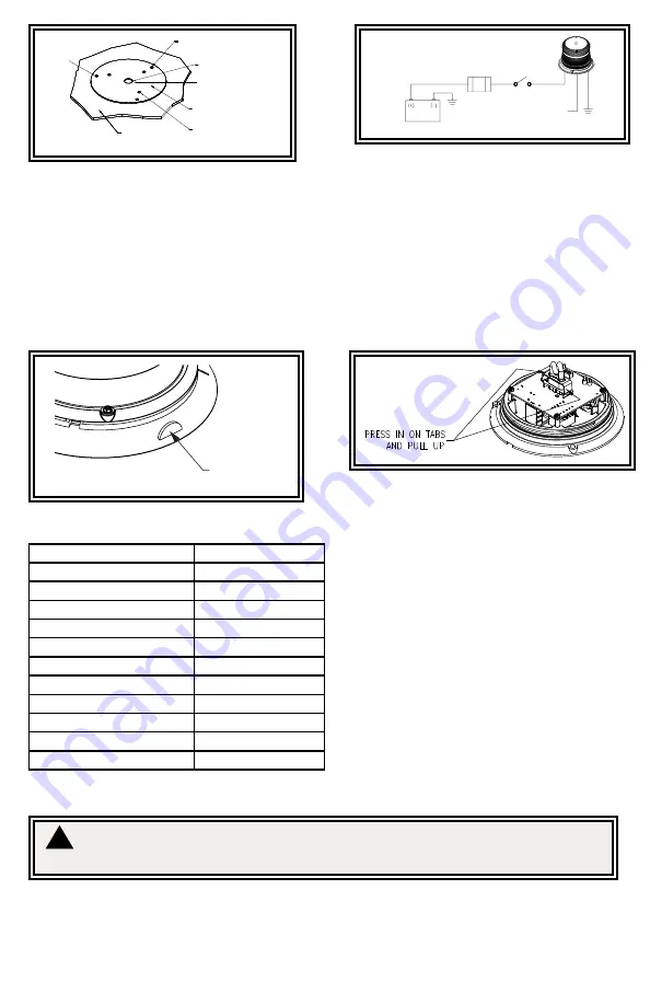
EXTERIOR MOUNTING
HOLE LOCATION
IF DESIRED DRILL
HOLE IN CENTER FOR
WIRE ACCESS
UNDERNEATH BEACON
BASE GASKET
MOUNTING
SURFACE
INTERIOR MOUNTING
HOLE LOCATION
3/4”
1/4”
Figure 1
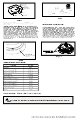
FUSE (10 AMP)
(USER SUPPLIED)
GROUND
GROUND
SWITCH
(USER SUPPLIED)
WHITE
N/C = DOUBLE FLASH
GROUNDED = QUAD FLASH
RED
BLACK
Maintenance & Troubleshooting:
Most strobe failures can be traced to wiring or battery problems. Check all
wiring and connections to insure the correct voltage is reaching the strobe
light. If the strobe operates erratically or stops completely, and the wiring
is not at fault, the flashtube is probably worn. To replace it, remove the
lens, and remove the flashtube by squeezing on the tabs on the side of the
tube holder and pulling off.
WARNING!
The strobe power supply is a high
voltage device. Wait 5 minutes after turning off power before removing lens
for access to internal parts. Plug in the new tube assembly. See Figure 4.
Note:
The connector is keyed to ensure proper orientation. Do not force. If
trouble continues, return product to your local dealer for warranty replace
-
ment, or call ECCO Customer Service for assistance (800) 635-5900.
Figure 3
Figure 4
Replacement Parts & Accessories:
PULL/ROLL TAB
UPWARD TO RELEASE
VACUUM
Figure 2
Description
Part Number
Flash Tube
R6501FT
Lens, 4” (replacement for 6550)
R6050LX*
Lens, 6” (replacement for 6570)
R6070LX*
Magnet Mount Kit
A6600MK
Self Leveling Bracket
A6600SLB
Branch Guard (for use with 6550)
A6050BG
Branch Guard (for use with 6570)
A6070BG
Dust Cover (for use with 6550)
A6050DC
Dust Cover (for use with 6570)
A6070DC
Vibration Dampening Kit
A6600VDK
Black Top
A6600BT
*where (X) indicates color:
A = Amber, B = Blue, C = Clear, G = Green, R = Red
NOTE: Operating the vehicle without the outer lens installed on the product may result in damage that will NOT be covered under
warranty.
!
Learn more about emergency and warning lighting on our website.


