3
T297 Fix 2
6004 0297 72
T297 Fix 4
6004 0297 74
T278 Fix 2
6102 3991 72
T278 Fix 4
6102 3991 74
A00470
6003 5786 98
HA00470
6003 6563 98
0.3
0.3 C
6001 1711 70
0.5
0.5 C
6001 1295 70
0.8
B0.8 C
6001 0966 70
1.1
1.1 C
6001 1068 70
6004 0218 92
Orifice
diameter
mm
Designation Part number Part number
Designation
Part number
Designation
Part number
Nozzle combinations
Paint nozzle Purge insert Paint needle Air cap
A0470
6003 5786 96
HA0470
6003 6563 96
HA0470FP
6004 0219 66
1.2
G1.2 C
6003 9212 70
1.4
G1.4 C
6003 9214 70
1.6
G1.6 C
6003 9216 70
1.8
G1.8 C
6003 9218 70
1.4
F1.4 C
6004 0114 70
1.4 G1.4 C
6003 9214 70
HA130470
6004 0030 70
6004 0218 94
1.2
F1.2 C
6004 0112 70
1.4
F1.4 C
6004 0114 70
1.6
F1.6 C
6004 0116 7
0
Paint nozzle designation
The letter “C” after the designation denotes certified and controlled nozzle.
Paint needle designation
The letter ”H” before the designation denotes tungsten-carbide design.
The letter ”HA13” before the designation denotes cylindrical point (self cleaning tip) only for nozzle 1.4.
The letter ”FP” after the designation denotes double cut tip.
Air cap designation
The letter “C” after the designation denotes certified and controlled nozzle.
The letter “Fix 2” after the denotes rotary air cap 2 x 180
o
vertical or horizontal spray pattern.
The letter “Fix 4” after the designation denotes rotary air cap 4 x 90
o
.
6004 0093 00
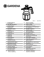
Flow control unit
for paint return
65130 F255
65130 F309
6003 9770 43
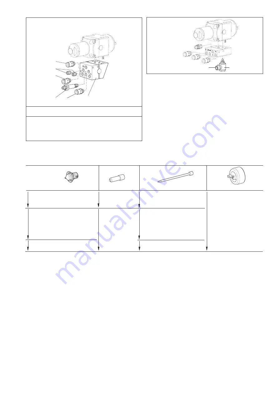
Mounting plate, compl.
for Robot with 13 mm guide pin
STL
– Operating air
F
– Paint
ZL
– Atomizing air
HL
– Fan air
Ref.
No. Part num ber
Qty
De scrip tion
1
–
1
Mounting plate
2
6003 9820 41
2
Coupling (G 1/8-8 mm)
3
6003 9820 31
1
Coupling (G 1/8-6 mm)
4
0194 1319 00
2
Set screw (SK6SS 8 x 10)
5
6003 9770 52
1
Nipple (G 1/8 8-mm SS)


