Wiring Instructions:
Important:
Disable power before wiring the beacon.
Notes:
1. Larger wires and tight connections will provide longer service life for components. For high current wires it is highly
recommended that terminal blocks or soldered connections be used with shrink tubing to protect the connections. Do
not use insulation displacement connectors (e.g., 3M Scotchlock type connectors).
2. Route wiring using grommets and sealant when passing through compartment walls. Minimize the number of splices
to reduce voltage drop. High ambient temperatures (e.g., under-hood) will significantly reduce the current carrying
capacity of wires, fuses, and circuit breakers. All wiring should conform to the minimum wire size and other recom-
mendations of the manufacturer and be protected from moving parts and hot surfaces. Looms, grommets, cable ties,
and similar installation hardware should be used to anchor and protect all wiring.
3. Fuses or circuit breakers should be located as close to the power takeoff points as possible and properly sized to
protect the wiring and devices.
4. Particular attention should be paid to the location and method of making electrical connections and splices to protect
these points from corrosion and loss of conductivity.
5. Ground termination should only be made to substantial chassis components, preferably directly to the vehicle battery.
6. Circuit breakers are very sensitive to high temperatures and will “false trip” when mounted in hot environments or
operated close to their capacity.
(+)
(-)
RED
BLACK
GROUND
GROUND
SWITCH
(USER SUPPLIED)
FUSE (5 AMP)
(USER SUPPLIED)
YELLOW
FLASH PATTERN SELECT
(ISOLATE WHEN NOT IN USE)
Figure 2
Maintenance:
This LED beacon has been designed for trouble free operation.
There are no periodic maintenance needs for this model.
Troubleshooting:
1. Most beacon failures, including intermittent or erratic operation
as well as failure of operation can be traced to wiring or battery
problems. Check all wiring, connections, fuse, switch, and bat-
tery voltage to insure that the correct voltage is reaching the
beacon.
2. If this has not remedied the problem, return product to your
local
dealer for warranty replacement
.
Note:
Operating the vehicle without the lens installed on
this product will result in damage that will not be covered
under warranty.
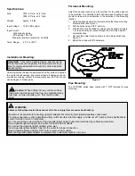
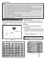
The wiring configuration is shown in Figure 2 below. All wiring
should be a minimum of 18AWG. A switch may be used to control
the on/off function. The black (negative) wire is connected to the
battery ground.
SAE J845 (2013) APPROVAL LEVELS
#
Pattern
FPM
7975A
7980A
7975B
7980B
7975C
7980C
7975G
7980G
7975R
7980R
1
Single
60
-
-
-
-
-
2
Single
120
CLASS 1
-
CLASS 1
-
-
3
Double
80
CLASS 1
CLASS 2 CLASS 1
-
-
4
Double
122
CLASS 1
-
CLASS 1
-
-
5
Triple
75
CLASS 1
-
CLASS 1
-
-
6
Quad
75
CLASS 1
CLASS 2 CLASS 1
-
-
7
Quad
122
CLASS 1
-
CLASS 1
-
-
8
Quint
75
CLASS 1
CLASS 2 CLASS 1
-
-
9
Burst 8
75
CLASS 1
CLASS 2 CLASS 1
-
-
10 Random
N/A
-
-
-
-
-
11 Steady
N/A
-
-
-
-
-
Flash Pattern Selection:
Flash patterns can be selected by touching the yellow wire to the
red power wire for less than a second. Contacting the yellow and
red wires for longer than a second toggles to the preceding flash
pattern.
Replacement Parts & Accessories:
Description
Part Number
Lens, 4”
R6050LX*
Lens, 6”
R6070LX*
Self Leveling Bracket
A6600SLB
Branch Guard
A6050BG
Branch Guard
A6070BG
Dust Cover
A6050DC
Dust Cover
A6070DC
Vibration Dampening Kit
A6600VDK
Black Top Decal
A6501BT
*where (X) indicates color:
A = Amber
B = Blue
C = Clear
G = Green
R = Red


