


- 22 -
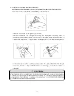
1. Checking high voltage generator
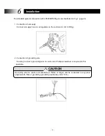
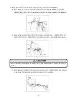
(1) Open the air valve and adjust the air pressure on the regulator to 0.3 to 0.4MPa to supply
air to the system. Be sure that there is no air leakage from any hose connection.
(2) Holding gun grip, switch on power to control unit. Green pilot lamp should be on. At this
point, no high voltage is at the gun head.
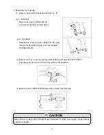
(3) Pull the gun trigger. When air flows through the nozzle, the air flow switch incorporated in
the control unit energizes high voltage to the system. The high voltage indicator (red lamp) will
be on . High voltage is present at the gun head as long as the red lamp is on. (High voltage is
not generated if the switch at the gun grip is off.)
Switch off the control unit as soon as the equipment check is complete.
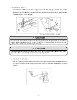
2. Paint adjustment
In this system, almost all synthetic resin paints can be sprayed with electrostatic energy and
there is no need to adjust the paint. Sometimes higher electrostatic effect can be obtained by
adjusting the solvent blend. There are some low electric resistance paints that cannot achieve
good electrostatic results. Check the resistance value of your paint using a resistance meter.
Good electrostatic results normally can be achieved by adjusting the resistance value to 15 to
70M ohm. If under 15MÙ, there will be some electrostatic effect, but too much paint will
bounce back in the direction of the gun and operator. This will necessitate higher exhaust
velocity and reduced transfer efficiency.
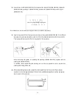
Electrostatic effect can be confirmed by spraying from the front side of a 20 to 30mm dia.
Steel pipe. It the paint wraps to the back side of the pipe, proper electrostatic effect is
confirmed.
No electrostatic results are expected when metallic, water-borne or other extremely low
resistance conductive paints are being used. In the case where high voltage is transmitted to
those types of paints, the high voltage shut-off circuit in the control unit may shut the system
down energizing the high voltage with buzzer alarm. Reset can be accomplished by turning
the power switch off and on.
Always use paint and solvent which have an ignition point at least 5°C higher than room
temperature
If there is any doubt, question or uncertainty in the suitability of your paint for this equipment,
consult our distributor or ECCO Finishing AB for assistance.
8
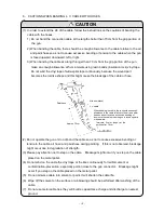
Checking before operation
CAUTION
CAUTION


