background image


- 23 - 


1.  Preparation for operation 

  (1) Fill the paint supply system.   

  The viscosity of the paint normally used for this equipment ranges in 9 to 30sec/FC #4, but not 

limited to viscosity. Consideration must me given to the type of paint and solvent, configuration of 

the part to be coated, required film thickness and, other conditions. It is recommended that the 

electric resistance value of the paint be measured before filling the supply system.   

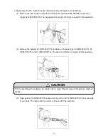
  (2) Start the material delivery system to supply paint to the spray gun.   

  Be  sure  the  supply  pump  is  operated  under  low  pressure  (approx.  0.  1Mpa)  using  the  air 

regulator  so  that  the  pump  will  begin  to  cycle  slowly  to  siphon  the  material  and  to  prime  the 

system. Increase pump pressure gradually until the material regulator at pump outlet shows 0.2 

to 0. 3 Mpa. If more precise fluid control is necessary or if the fluid flow pulsates, consider adding 

a fluid regulator to the system between the material supply system and the electrostatic gun.   


Confirm again that the control unit power is off. 


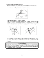
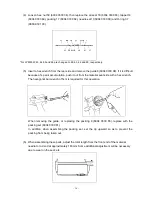
  (3) Inject the paint from the gun tip. 

  Turn off atomization air and pull the trigger to start flowing paint from the spray gun.    Since there 

may be air entrapped in the supply line continue t o flow paint until all remaining air pockets in 

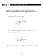
paint hose are removed.    Paint output can be increased by turning adjuster valve at rear right 

side of gun body counter-clockwise and stopped by fully turning it clockwise.    When painting is 

ceased, turn the valve fully clockwise to stop paint output, or curtail the pump pressure.   

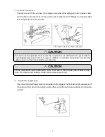
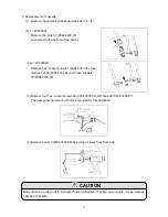
(4) Increase atomizing air gradually to observe the degree of atomization.   

Adjust  atomizing  air  pressure  to  0.2  to  0.3  MPa  and  pull  trigger  to  observe  the  degree  of 

atomization.  Please  understand  that  only  enough  atomization  to  break  up  the  necessary  paint 

flow should be used. Excessive pressures will only accomplish increased over-spray and waste. 

This  atomizing  air  pressure  should  be  adjusted  to  suit  the  nozzle  and  the  requirements  of  the 

process.   

In addition, this gun uses inside airtight structure in order to prevent the paint come into gun body. 

Small volumes of air always flow out from needle. Therefore it is not malfunction if there is sound 

of airflow from needle.   

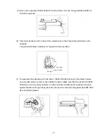
(5) The spray pattern can be widened by turning the pattern width adjusting valve at the left rear of 

the gun body counter-clockwise and narrowed by turning it clockwise.     


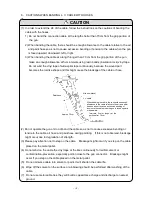
Make sure that air is not leaking when returning the connection of the air hose and the trigger to 
the  original  position.    When  air  is  discharged  with  the  power  supply  on,  a  high  voltage  is 
generated whether it is operating or not. 
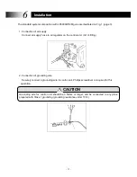
 

Operation 

CAUTION


WARNING 

Summary of Contents for Xtatic LP6000M

Page 1: ...S LP6000M This manual contains important information on warnings and cautions Read the manual thoroughly before starting to operate this equipment and follow the instructions Always keep the manual ha...

Page 2: ...is spray gun is to be used in combination with the electrostatic coating controller Model BPS115 The separate instruction manual for the controller should be used as a reference for the operation of t...

Page 3: ...5 Exploded Diagram and names of parts 7 6 Installation 14 7 Safety control 19 8 Checking before operation 21 9 Operation 22 10 Maintenance 25 11 Trouble shooting on spray technique 27 12 Trouble shoot...

Page 4: ...own below and in the pages that follow are the basic minimum safety precautions in connection with use of our product Safety precautions are classified into three categories based on the severity of h...

Page 5: ...structure coating booth is a rectangle shaped area with a side of 1 5m opening width both sides and the other side of 2 5m closer side of the opening part This entire area should have a static charge...

Page 6: ...ne of the equipment Fig 1 An example of a system composition Control unit should be installed outside the spray booth and at least 1 5m from the opening or entrance WARNING Air electrostatic hand spra...

Page 7: ...ng valve Barrel Pattern air adjusting valve Power cable Hook Trigger Grip Paint hose milky white color Pattern air adjusting valve Material adjusting valve Material adjusting valve Hook Barrel Grip Tr...

Page 8: ...9 EC EN 50050 2001 Certification Sira 10ATEX5053X Sira Test Certification Ltd Rake Lane Eccleston Chester CH4 9JN England The cable length can be extended up to 30m by combining the extension and con...

Page 9: ...6 our Distributor or ECCO Finishing AB...

Page 10: ...loaded U packings assure long working life 5 High quality coating Wide angle multi step injection by flat spray nozzles can achieve beautiful finishes on flat surfaces particularly in metallic coating...

Page 11: ...8 1 AIR ELECTROSTATIC GUN LP6000W 5 Breakdown drawing A B C...

Page 12: ...04 0330 83 Air valve seat 1 54 6004 0330 24 Nut 1 19 6004 0330 72 Spring 1 55 6004 0330 23 Hose support 1 20 6004 0330 73 Spring 1 56 6004 0330 22 Nylon screw 1 21 6004 0330 74 Spring 1 57 6004 0330 1...

Page 13: ...10 2 AIR ELECTROSTATIC GUN LP6000S Breakdown drawing B A...

Page 14: ...4 0330 83 Air valve seat 1 54 6004 0330 21 Stay 1 19 6004 0330 72 Spring 1 55 6004 0330 20 Packing 2 20 6004 0330 73 Spring 1 56 6004 0330 26 Connector 2 21 6004 0330 74 Spring 1 57 6004 0330 18 Tube...

Page 15: ...12 3 AIR ELECTROSTATIC GUN LP6000M Breakdown drawing...

Page 16: ...e seat 1 54 6004 0330 21 Stay 1 19 6004 0330 72 Spring 1 55 6004 0330 20 Packing 1 20 6004 0330 73 Spring 1 56 6004 0330 26 Connector 2 21 6004 0330 74 Spring 1 57 6004 0330 37 Spiral tube set 1 22 60...

Page 17: ...No Part No Part Name Qty Note No Part No Part Name Qty Note 1 6004 0330 44 60 Air Cap 1 4 6004 0330 46 Stopper Ring 1 2 6004 0330 51 Paint Nozzle 1 1 1 5 6004 0330 47 Charge Electrode 1 3 6004 0330 45...

Page 18: ...egulator on the control unit G 1 4 fitting 2 Connection of grounding wire Securely connect a grounding wire to control unit Phillips screwdriver is required for this operation Grounding wire for contr...

Page 19: ...hat the surface of the stopper may closely contact to the hexagonal plain part while loosening the nut Fix the cable and the air hose with the insulation lock at the position 70 to 80cm from the gun A...

Page 20: ...un in order to prevent applying excessive force to the gun In addition do not allow the spanner to contact the cable connector at the time of attaching or removing Effective atomization can be obtaine...

Page 21: ...excessive bending or tensile to the cable air hose and paint hose during painting If this is not observed breakage might occur due to degradation of strength 3 Please pay attention not to step on the...

Page 22: ...mount joint Pay attention when attaching and removing Air cap can be slightly tightened by fingers If it is tightened too much paint nozzle might loosen when changing the direction of the air cap Thi...

Page 23: ...if they are close to or near to booth entrance Handle coating equipment with bare hands Though the gun grip is grounded through the cable and control unit wearing of non conductive gloves on hands me...

Page 24: ...e spray gun approaches a grounded item In cases where an insulated paint supply pump is being used for lower electric resistance paint like metallic paints woodworking paints emulsion paint etc the gu...

Page 25: ...ults Check the resistance value of your paint using a resistance meter Good electrostatic results normally can be achieved by adjusting the resistance value to 15 to 70M ohm If under 15M there will be...

Page 26: ...paint until all remaining air pockets in paint hose are removed Paint output can be increased by turning adjuster valve at rear right side of gun body counter clockwise and stopped by fully turning i...

Page 27: ...parking in a case of a rapid approach gun to ground Do not touch the nozzle during high voltage is applied 3 When not painting always switch off the power to the control unit Never leave the spray gun...

Page 28: ...ing in the pump to bleed through the return 5 Pull gun trigger to reduce paint pressure remaining in hose and gun 6 Flush cleaning solvent through the system until the fluid passages are clear of pain...

Page 29: ...are should be taken that they do not fall on the floor 5 It is possible that the rear upper part of the gun body may become warm due to heat produced by the cascade This condition is perfectly normal...

Page 30: ...not to damage hoses and cables with heavy objects or vehicles Before any maintenance and or service work make sure that the power switch is turned off on the control unit and the air fluid pressure is...

Page 31: ...2 Too much paint bouncing back Possible causes Solution 1 Too long spray distance 1 Keep the distance at 150 to 200mm 2 Too high atomizing air pressure 2 Lower the pressure 3 Too low paint resistance...

Page 32: ...causes Solutions 1 Too high booth temperature or too fast evaporating solvent 1 Adjust the temperature or change to slower solvent 2 Higher object temperature 2 Adjust drying furnace temperature 3 To...

Page 33: ...g system 2 Inadequate selection of solvent 2 Consult material supplier 12 Bubbles on coated surface Possible causes Solutions 1 Contaminated atomizing air 1 Clean or replace filter in air control 2 In...

Page 34: ...r 6 5 5 Extremely poor paint output air pressure 5 Increase output or lower atomizing 9 1 2 Paint output is decreased Possible causes Solutions Ref 1 Trouble in paint supply system 1 Check to be sure...

Page 35: ...3 Fatigue of the spring 3 Replace the spring 13 2 4 Wear or breakage of the O ring 4 Replace the O ring 13 2 6 Air leakage from the air regulator Possible causes Solutions Ref 1 Worn out or damaged O...

Page 36: ...when insulation stand is used Possible causes Solutions Ref 1 Paint has accumulated on the gun extension 1 Clean the extension 7 2 Paint has accumulated on the front end of the paint hose 2 Clean the...

Page 37: ...and parts No 1 Replacement of paint seat Paint seat and needle should be replaced together 1 Remove paint seat 33 6004 0330 48 at front end of gun barrel Its removal and replacement should be done wit...

Page 38: ...operation 2 Remove the adapter 22 6004 0330 75 and take out three springs 19 6004 0330 72 20 6004 0330 73 and 21 6004 0330 74 The spanner of 8mm is required for this operation When assembling the ada...

Page 39: ...paint accumulation push it out from the material seat side with a hex wrench The hexagonal bar wrench of 5cm is required for this operation When removing the guide or replacing the packing 9 6004 0330...

Page 40: ...004 0330 38 then remove nut 54 6004 0330 24 and hose support 55 6004 0330 23 3 Remove four hex socket screws 48 6004 0330 36 and hook 29 6004 0330 87 The hexagonal bar wench of 3mm is required for thi...

Page 41: ...required for this operation 7 To assemble the cascade put it into body 1 6004 0330 60 turning it a few times to make sure the lead wires are correct then attach the barrel Make sure that the cushion...

Page 42: ...3 9302 00 at the tip of adjuster Air leaked into the gun is discharged from the dial portion of the adjuster when the O ring is damaged If operation is continued without replacing such O ring there mi...

Page 43: ...use ECCO Finishing AB In house ECCO Finishing AB In house ECCO Finishing AB In house ECCO Finishing AB In house ECCO Finishing AB In house ECCO Finishing AB In house ECCO Finishing AB In house ECCO Fi...

Page 44: ...Japan In these circumstances any costs that may be incurred on repair or freight shall be the responsibility of the Purchaser In the event also of failure caused by use in conjunction with a hose or...

Page 45: ...ECCO FINISHING AB Box 93 S 532 22 SKARA Sweden Tel 46 0 511 134 45 Fax 46 0 511 180 13 E mail info eccofinishing com www eccofinishing com...

Reviews: