EXCEL 50 INSTALLATION INSTRUCTIONS
EN1B-0101
22
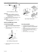
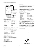
Fig. 40. Connecting the power supply.
IMPORTANT
If there already are additional transformers, for
example supplying actuators or active sensors:
— Connect the 24 Vac (-) (secondary side) of the
transformers together.
14.
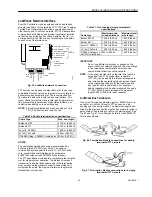
Plug the flat strip cables into the sockets of the terminal
blocks and the housing as is shown in Fig. 41.
IMPORTANT
Make sure pins match properly with their sockets
when mating connectors.
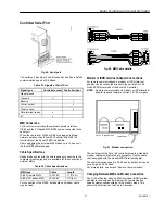
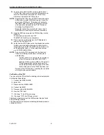
Fig. 41. Plug-in of flat strip cables.
Adjusting the MMI Display Contrast
Front Door Mounted with MMI
1.
Unplug the screw terminal block B
or
Flat Strip cable to
Port B while the controller is connected to the power
supply.
2.
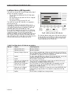
Adjust the display contrast with a slotted screwdriver or
a cross-tip screwdriver.
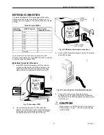
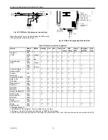
Fig. 42. Adjusting the display contrast.
3.
Attach screw terminal block B
or
connect Flat Strip
Cable to Port B.
DIN-rail Mounted with MMI
1.
Unmount the controller from the DIN-rail.
2.
Unplug the screw terminal block B
or
Flat Strip cable to
Port B while the controller is connected to the power
supply.
3.
Adjust the display contrast with a slotted screwdriver or
a cross-tip screwdriver as is shown in Fig. 42.
4.
Attach screw terminal block B
or
connect Flat Strip
Cable to Port B.
5.
Mount the controller on the DIN-rail again.


