background image


LonWorks Twisted Pair Control Module User's Guide 

       17 

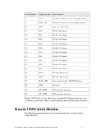
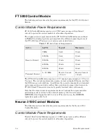
The supply current requirements for the control modules are outlined in 

Table 8

which includes peak requirements for the different operating states of the 

Neuron Chip.  The control modules require a 5 V ±5% power supply.  The current 

requirements are characterized for maximum number of devices on the channel 

with I/O pins programmed as outputs at a logic low level with no load. 
The values in 

Table 8

 are subject to change.  Please consult current data sheets 

for the latest information. 

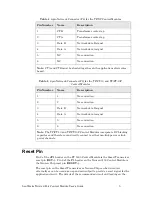
Table 8

. Typical Control 5 Volt Current Requirements 

Control Module 

Typical  DC Characteristics  (+5.0 V)


Active, Receive  (mA) 

Active, Transmit  (mA) 

TP/FT-10 (5 MHz) 

25 

40 

TP/FT-10F (10 MHz) 

50 

60 

TP/XF-78 (5 MHz) 

35 

45 

TP/XF-78F (10 MHz) 

50 

60 

TP/XF-1250 (10 MHz) 

55 

80 

Notes

1.


Assumes internal I/O pullups are disabled and I/O lines are not connected 

to a load. 

2.


Assumes SERVICE~ pullup is enabled.  

3.


Includes CMOS EPROM or flash chip running typical application with 

system code. 

4.


These figures include typical PROM current consumption of 4 mA at 5 

MHz or 5 mA at 10 MHz; the TP/FT-10F and TP/XF-78F figures include 

flash memory reads, however, 

flash memory writes require an 

additional

 50 mA

.  These figures exclude current due to loading on the 

I/O connector pins. 


Summary of Contents for LONWORKS FT 5000

Page 1: ...LONWORKS Twisted Pair Control Module User s Guide 078 0015 01F...

Page 2: ...her than Echelon and referenced in this document have been described for illustrative purposes only and may not have been tested by Echelon It is the responsibility of the customer to determine the su...

Page 3: ...e modules Table 1 LONWORKS Twisted Pair Control Modules Module Model Number Features FT 5000 Control Module 55040R 10 Transformer isolated free topology 78 kbps communications up to 80 MHz system cloc...

Page 4: ...t are used for developing installing operating and maintaining them LONMARK Application Layer Interoperability Guidelines This manual describes design guidelines for developing applications for open i...

Page 5: ...electrotechnique1 CENELEC EN 55022 Information technology equipment Radio disturbance characteristics Limits and methods of measurement Comit international sp cial des perturbations radio lectriques2...

Page 6: ...ology Device Data o Toshiba Neuron Chip TMPN3150 3120 o Cypress Neuron Chip Technical Reference Manual See the Echelon Series 5000 Chip Data Book 005 0199 01B or FT 3120 FT 3150 Smart Transceiver Data...

Page 7: ...nd Connection 19 Performance Characteristics and Cabling 20 Free Topology TP FT 10 and TP FT 10F 20 Wire Characteristics 21 Cable Terminations Free Topology 21 Cable Terminations Doubly Terminated Bus...

Page 8: ...velopment and Export 40 NodeBuilder FX Development Tool 40 Configuration for FT 5000 Control Modules 41 Configuration for Neuron 3150 Control Modules 43 Programming 45 Mini FX Evaluation Kit 45 ShortS...

Page 9: ...nterface FT 5000 Control Modules interface to the device application electronics and to the network through the JP1 connector Neuron 3150 Control Modules interface to the device application electronic...

Page 10: ...e signals The I O signals are connected directly to the FT 5000 Smart Transceiver without buffering MOV_GND IO2 IO0 CP2_TXLED SVC RST FT_NETA IO10 IO8 IO6 IO4 SCL SDA_CS1 IO11 FT_NETB IO3 IO1 IO5 IO9...

Page 11: ...objects 17 IO6 IO6 for I O objects 18 IO7 IO7 for I O objects 19 IO8 IO8 for I O objects 20 IO9 IO9 for I O objects 21 IO10 IO10 for I O objects 22 IO11 IO11 for I O objects 23 MOV_GND Return ground...

Page 12: ...s are connected directly to the Neuron 3150 Chip without buffering Table 3 18 pin I O Connector P1 for Neuron 3150 Control Modules Pin Number Name Description 1 NC No Connect 2 IO0 IO0 for I O objects...

Page 13: ...2 2 No connection 3 Data B Network data B signal 4 Data A Network data A signal 5 5 No connection 6 6 No connection Note The TP FT 10 and TP FT 10F Control Modules incorporate DC blocking capacitors a...

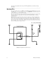
Page 14: ...ibed in the Series 5000 Chip Data Book or Neuron Chip Data Book Figure 2 shows a typical circuit for the device service pin Typical applications do not require debounce conditioning of momentary push...

Page 15: ...ntrol Module User s Guide 7 2 Mechanical Considerations This chapter discusses the mechanical footprint and connectors of the Twisted Pair Control Modules Details of mounting to an application electro...

Page 16: ...igure 4 shows the mechanical footprint for an FT 5000 Control Module You can solder the module directly to your PCB as a through hole part or mount it in a connector The module includes a male Samtec...

Page 17: ...25 inch 0 64 mm square posts of P1 and P2 are inserted into the sockets they provide enough holding strength 3 oz 85 g pin to secure the control module against shock and vibration to the operating lim...

Page 18: ...10 Mechanical Considerations Figure 5 Neuron 3150 Control Module Mechanical Footprint...

Page 19: ...S Methode 9000 209 303 9000 106 303 Advanced Interconnections BC 009 124TL BC006 123TL Not recommended for use with the TP FT 10 or TP FT 10F Control Modules Figure 6 Recommended Spacing between the...

Page 20: ...12 Mechanical Considerations Figure 8 Vertical Component Profile for the Control Modules...

Page 21: ...LonWorks Twisted Pair Control Module User s Guide 13 Figure 9 Required Pad Layout for Application Electronics Board...

Page 22: ......

Page 23: ...dule User s Guide 15 3 Power Requirements This section describes the power requirements for the control modules as well as considerations for noise filtering in order to comply with both conducted and...

Page 24: ...A Receive Current 18 mA The FT 5000 Control Module requires a 3 3 V nominal power supply 3 0 V to 3 6 V range The current requirements assume no load on digital I O pins and that the I O lines are not...

Page 25: ...Typical Control Module 5 Volt Current Requirements Control Module Typical DC Characteristics 5 0 V Active Receive mA Active Transmit mA TP FT 10 5 MHz 25 40 TP FT 10F 10 MHz 50 60 TP XF 78 5 MHz 35 4...

Page 26: ......

Page 27: ...s Guide 19 4 Network Cabling and Connection This chapter addresses cabling and termination for the FT 5000 Control Module and the Neuron 3150 Control Modules TP FT 10 TP FT 10F TP XF 78 TP XF 78F and...

Page 28: ...78 TP XF 78F Bus 1400 m 4600 feet worst case with 3 m 10 feet stubs with 22 AWG 0 65 mm Level IV Cable 64 at 0 to 70 C 44 at 40 to 85 C TPT User s Guide 078 0025 01 Control Module Data Sheet 003 0121...

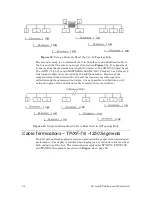
Page 29: ...rom the Echelon Web site www echelon com Cable Terminations Free Topology In a TP FT 10 free topology segment only one termination is required and can be placed anywhere on the free topology segment T...

Page 30: ...IV AWG 22 0 65 mm or AWG 24 0 511 mm ANSI TIA EIA 568 B 2 2001 Category 5 or Category 6 twisted pair cable Stubs where permitted Level IV AWG 24 0 511 mm cable Level IV AWG 22 cable or AWG 24 0 511 m...

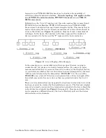
Page 31: ...igure 11 8 in 16 Topology Rule Example In the example we see an installation with six groups of devices varying in number from 2 to 8 devices in a doubly terminated bus By using a 16 meter measurement...

Page 32: ...al cable Because of the complex interactions between the bus and the transceivers with regard to reflections and transmission line delays it is not possible to substitute an LC network in place of the...

Page 33: ...LonWorks Twisted Pair Control Module User s Guide 25 Figure 14 Required Bus Termination for TP XF 78 and TP XF 1250 Twisted Pair Networks...

Page 34: ......

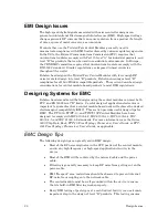
Page 35: ...ign Issues This chapter describes design issues including a discussion of Electromagnetic Interference EMI and Electrostatic Discharge ESD and Designing for Interoperability This chapter applies to bo...

Page 36: ...strated that designs using the control modules can meet both FCC and EN55022 level B limits Careful design of application electronics is important to guarantee that a control module based node will ac...

Page 37: ...attenuation over the 30 to 500 MHz range A choke adds a few pF of differential capacitance to the data communication lines and therefore reduces network performance and can affect interoperability In...

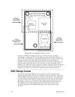
Page 38: ...nce return to an external metal package if there is one If there is no metal package then this ground area should connect to the ground areas near the power supply connector and the external I O conne...

Page 39: ...es Area 1 the EMI Radiated Keepout Area covers the Neuron Chip and the PROM This is the area of the control module that generates the most RF noise Cables long metal chassis parts and drive circuits f...

Page 40: ...hassis parts and other primary side components at least 3 8 mm 0 15 inches away from the secondary area on the control module and the network connector ESD Design Issues Electrostatic Discharge ESD is...

Page 41: ...lamping of the exposed lines is required to shunt the ESD current Consult a good text on EMC for advice about ESD and transient protection for exposed circuit lines In general exposed lines require di...

Page 42: ...out guideline for the application electronics board is recommended Mutual capacitance of data pair conductors differential capacitance from the twisted pair medium tap connector to the connector which...

Page 43: ...e 35 6 Programming Considerations This section explains the integration of control modules using the NodeBuilder FX Development tool It covers considerations relating to memory specifications device d...

Page 44: ...r the Aardvark I2C SPI Host Adapter with the Flash Center Memory Programmer software Rename the NME application image file that is generated by the NodeBuilder tool to a HEX file Select the memory par...

Page 45: ...the following tasks 1 Reset the device by pressing and holding the device s Reset button If the device does not have a Reset button temporarily connect the RST pin pin 2 of the JP1 header of the cont...

Page 46: ...is in the EEPROM device During device re initialization and reset the FT 5000 Smart Transceiver reads these bytes and copies the default chip configuration including memory map and mode table to the...

Page 47: ...Modules have a 10 MHz input clock and require an Atmel AT29C257 90J 32 KB AT29C517 90J 64 KB total 56 KB usable 8 KB unusable or AT29C010A 90J 128 KB total 56 KB usable 72 KB unusable flash memory Ta...

Page 48: ...T 5000 Control Module see the ShortStack FX User s Guide for more information about developing ShortStack devices Important Table 14 lists the minimum required Neuron firmware version for applications...

Page 49: ...pportunity to select predefined hardware templates At a later point in the development process you can access the hardware template through the Development and Release folders of the project pane Afte...

Page 50: ...sion 19 Memory Tab Off Chip ROM N A Extended Non Volatile 0x4000 to 0xC7FF Extended On Chip RAM 0xC800 to 0xE7FF I O N A On Chip ROM 0x0000 to 0x3FFF On Chip RAM 0xE800 to 0xEFFF Mandatory EEPROM 0xF0...

Page 51: ...ol Modules NodeBuilder Hardware Template Specification Neuron 3150 Control Module TP FT 10 TP XF 78 TP XF 1250 Hardware Tab Platform Custom Custom Custom Transceiver Type TP FT 10 TP XF 78 TP XF 1250...

Page 52: ...Clock Speed 10 MHz 10 MHz System Image Version Default Default Memory Tab Off Chip ROM 0 0 Off Chip Non Volatile 0x0000 to 0x7FFF for 32Kx8 0x0000 to 0xDFFF for 32Kx8 0x0000 to 0x7FFF for 32Kx8 0x000...

Page 53: ...Evaluation Kit is a tool for evaluating the development of control network applications with the ISO IEC 14908 1 ANSI CEA 709 1 and EN14908 Control Network Protocol You can use the Mini FX Evaluation...

Page 54: ...Echelon does provide the serial driver API and an example driver for a specific host processor Currently example drivers are available for an Atmel ARM7 microprocessor and an Altera Nios II embedded p...

Page 55: ...www echelon com...
Reviews: