34
Design Issues
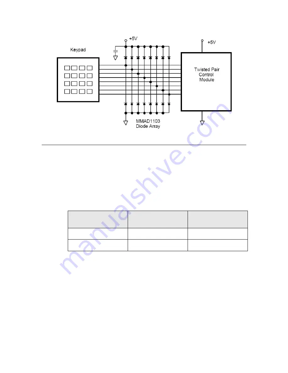
Figure 17
. Example of Diode Clamping Protection for Control Module I/O Lines
Designing for Interoperability
To meet the L
ON
W
ORKS
interoperability guidelines for the Neuron 3150 TP/XF-
78, TP/XF-78F, and TP/XF-1250 devices, the following printed circuit layout
guideline for the application electronics board is recommended.
Mutual capacitance of data pair conductors (differential capacitance) from the
twisted pair medium tap connector to the connector which mates to the TP/XF
control module
P2
header must be kept within the maximum limit specified in
Table 10
. Mutual Capacitance of Data Pair Conductors
Module type
Maximum mutual
capacitance
Maximum PCB trace
lengths
TP/XF-78, -78F
5 pF
50 mm
TP/XF-1250
2 pF
20 mm
Summary of Contents for LONWORKS FT 5000
Page 1: ...LONWORKS Twisted Pair Control Module User s Guide 078 0015 01F...
Page 18: ...10 Mechanical Considerations Figure 5 Neuron 3150 Control Module Mechanical Footprint...
Page 20: ...12 Mechanical Considerations Figure 8 Vertical Component Profile for the Control Modules...
Page 22: ......
Page 26: ......
Page 34: ......
Page 55: ...www echelon com...


