LonWorks Twisted Pair Control Module User's Guide
37
Table 11
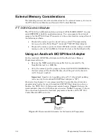
. Pin Connections for Aardvark Programmer and JP1 Header
Aardvark Programmer Header
FT 5000 Control Module JP1 Header
Pin
Signal
Pin
Signal
1
ACS_2_SCL
8
SCL
3
ACS_1_SDA
9
SDA_CS1~
10
ARST~
2
RST~
The connection between the Aardvark programmer header’s
ARST~
signal and
the FT 5000 Control Module
JP1
connector’s
RST~
signal ensures that the FT
5000 Smart Transceiver is held in reset during device programming.
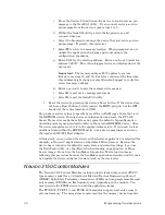
Clearing the Non-Volatile Memory
In general, if you have a working device, you should not need to clear the
external EEPROM non-volatile memory for a Series 5000 chip. For a working
device, you can receive a service-pin message and reload the non-volatile memory
from the network as needed. However, if it should become necessary to clear the
EEPROM non-volatile memory (for example, during device development),
perform the following tasks:
1.
Reset the device by pressing and holding the device’s Reset button. If the
device does not have a Reset button, temporarily connect the
RST~
pin
(pin 2 of the
JP1
header) of the control module to GND to hold the chip in
the reset state.
2.
Temporarily connect the EEPROM's SCL pin (pin 8 of the
JP1
header) to
GND.
3.
Release the device’s Reset button (or remove the GND connection from
the
RST~
pin).
4.
Wait a few seconds until the device’s Service Pin LED is illuminated (on
solid, not flashing). If the device does not have a Service Pin LED,
connect a logic analyzer or oscilloscope to the
SVC~
pin (pin 10 of the
JP1
header) of the control module and verify that it changes state (low to
high) at a 76 Hz rate.
5.
Disconnect the EEPROM's SCL pin from GND.
6.
Use the NodeUtil utility to set the memory configuration and set the
state for the device:
a.
Connect the PC that will run the NodeUtil utility to the same
network interface that connects to the device. For example, if you
connect to the device using
LON1
, connect the NodeUtil utility to
LON1
.
b.
Start the NodeUtil utility.
Summary of Contents for LONWORKS FT 5000
Page 1: ...LONWORKS Twisted Pair Control Module User s Guide 078 0015 01F...
Page 18: ...10 Mechanical Considerations Figure 5 Neuron 3150 Control Module Mechanical Footprint...
Page 20: ...12 Mechanical Considerations Figure 8 Vertical Component Profile for the Control Modules...
Page 22: ......
Page 26: ......
Page 34: ......
Page 55: ...www echelon com...

