10
Installation of PCBs Into Crossover Assembly
After allowing the boards to cure overnight, you’re now ready to install the new PCBs into the
factory crossover assembly.
1.
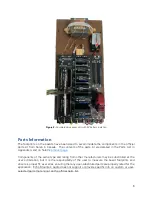
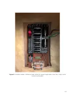
Align the PCB mounting holes with the four snap
-
lock board mounts on the crossover
board, and gently snap each corner into place, one at a time. The board orientation should
match that shown in Figure 3.
2.
Insert the stripped ends of the black and red wires from the binding posts into the plated
through holes E1 (IN+, red wire) and E2 (IN
-
, black wire). Solder both wires to the PCB.
3.
Insert the tinned ends of the two wires from the inductor mounted on the crossover
assembly to pads E3 and E4 (also denoted by “L2” on the PCB silkscreen). Solder both
wires to the PCB.
4.
Obtain one of the 9V battery connectors with flying leads. Cut the leads down to about
1
-
1.5 inches in length, strip the ends, and insert the red wire into the PCB pad marked 9V
battery “+” (upper right corner of the PCB). Insert the black wire into the PCB pad to the
left of that. Solder both wires to the PCB.
5.
Obtain one of the 9V battery clips and the double
-
sided tape and cut a piece of tape to fit
to the bottom surface of the mounting clip. Affix one side of the tape to the bottom of
the clip and press down to adhere.
6.
Place a 9V battery in the clip, center it, and then remove the protective layer on the
exposed side of double
-
sided tape. Place the battery and clip down on the right side of
the crossover assembly mounting plate, choosing the location such that there is enough
room to remove/install the battery, and enough room to attach the battery connector and
wires. Use Figure 3 as a guide on placement. Remove the battery from the clip while
holding the clip down to the surface (you don’t want to lift the tape up inadvertently).
Press down firmly on the bottom of the clip to increase the adhesion of the tape. If the
tape accidentally lifts from the crossover, start over with a fresh piece of tape, as it will
take small debris from the fiberboard with it, and won’t adhere as well on the next
attempt. This may sound complicated from the detailed description, but it’s quite simple.
Note that the battery can slide back and forth in the clip, so the exact placement of the
clip is not critical.
7.
If remnants of the old strain relief clamp (refer to Step 6 of the “Removing Crossover
from Speaker” section) are still in place, remove them carefully with a putty knife or other
tool (the old, brittle adhesive should chip away easily). If this is proving difficult, leave it
there and move to the next step.
8.
In the location of the old strain relief clamp (or adjacent to it, if you couldn’t get it fully
removed), place an adhesive
-
backed zip tie mount and press down to adhere.
9.
Repeat steps 1 through 8 for the other PCB and crossover assembly.


