16
W
IRE
I
NSTALLATION
P
ERIPHERAL
W
IRE
7.1.1 Minimum Installation Dimensions
for Multiple Robots
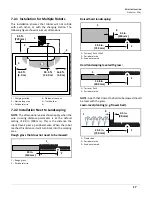
This installation ensures that robots will not collide
with each other or with the charging station. The
following figure shows minimum dimensions.
If the station loop wire is completely
inside
of the
peripheral wire, install as shown:
If the station loop wire is partially inside of the periph-
eral wire, install as shown:
7.2 Peripheral Wire
The peripheral wire defines the working area.
•
Each peripheral wire is assigned to a different
signal channel in the charging station (the
charging station must contain one signal channel
board for each peripheral wire).
•
Each peripheral wire must overlap with its neigh-
boring one.
•
Each pair of peripheral wires which overlap must
be designated as neighboring fields.
•
The ends of each peripheral wire are connected
to a single charging station.
•
Install the wire in a clockwise direction around
the field.
•
Do not cross or form loops with the wire.
•
Minimum wire length is 656 ft. (200 m). If this
minimum length is not possible, install Inductive
Coil Kit, P/N M114000040.
•
Maximum peripheral wire length is 3937 ft.
(1,200 m).
Use a second charging station when:
•
the total length of the peripheral wire (including
islands and pseudo-islands) exceeds 3,281 ft.
(1,000 m)
•
more than five obstacles are on the track border
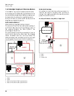
Peripheral wire installation angles must be greater
than 90°, with a radius greater than or equal to 3.3 ft.
(1.0 m).
Obstacles may require specific placement of the
peripheral wire, or the use of islands or pseudo-islands.
1 – Station loop wire
2 – Peripheral wire
3 – Charging station
1 – Station loop wire
2 – Peripheral wire
ϲ͘ϱŌ͘
(2.0 m)
ϭϲ͘ϱŌ͘
(5.0 m)
Zϴ͘ϱŌ͘
(2.5 m)
ϭϭ͘ϱŌ͘
(3.5 m)
1
2
3
ϲ͘ϱŌ͘
(2 m)
ϭϲ͘ϱŌ͘
(5.0 m)
1
2
1 – Peripheral wire
1
шϯ͘ϯŌ͘
;шϭŵͿ
шϵϬΣ
1


