G
RASS
T
RIMMER
/B
RUSH
C
UTTER
O
PERATOR
'
S
M
ANUAL
19
U
-
HANDLE
INSTALLATION
Tools Required: 8mm x 10mm Open End Wrench, Screwdriver, 3mm
and 4mm Hex Wrench, Pliers
Parts Required: U-Handle/Blade Conversion Kit P/N 99944200521.
NOTE
For Model SRM-231U use steps 10, 12-14, 16, 17.
1.
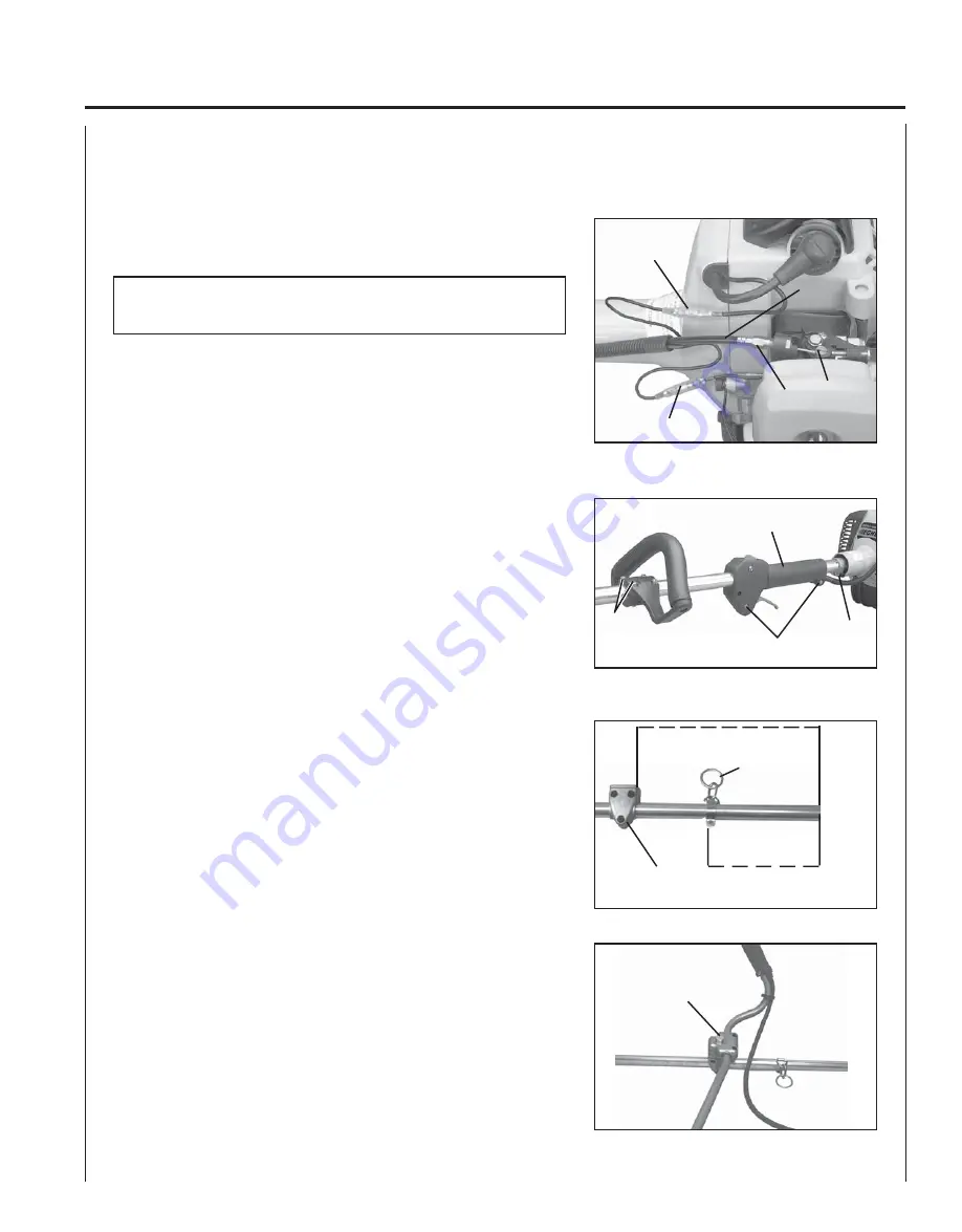
Disconnect ignition stop leads (A) and (B).
2.
Remove inner throttle linkage from carburetor swivel (C).
3.
Remove throttle linkage (D) from throttle linkage fixture (E).
4.
Loosen bolt (F) and pull drive shaft assembly from clutch case.
5.
Loosen two (2) rear handle screws (G) and pull rear handle (H) from
the drive shaft assembly.
6.
Loosen four (4) screws (I) and remove front handle.
7.
Install harness hook (J).
8.
Position lower U-Handle bracket (K) 400mm (15-3/4 in.) from
engine end of drive shaft. Secure with three (3) 5mm x 30mm
bolts.
9.
Position harness hook 220mm (8-5/8 in.) from engine end of drive
shaft assembly. DO NOT tighten at this time.
10. Install upper U-Handle and bracket on lower bracket and secure
with one (1) 8mm x 55mm bolt (L) and large circular washer.
11. Install power head and align gear box, power head and U-Handles.
Tighten all screws.
L
400 mm (15-3/4 in.)
220 mm
(8-21/32 in.)
ENGINE
END
J
K
F
G
I
H
A
B
D
E
C


