background image

7E

4F

Étape 4

(filtre d'arrêt)

SYSTÈME DE FILTRAGE À 4 ÉTAPES

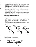
Ce pulvérisateur de sac à dos est doté d'un système de filtration à 4 étapes (voir la
Figure 1). L'étape 1 est un panier-filtre incorporé dans l'ouverture de la cuve où l'on
ajoute le fluide. Les filtres des étapes 2 et 3 se trouvent à l'entrée du cylindre de
pression. L'étape 2 est un tube à filtre amovible. L'étape 3 est une cartouche à filtre
amovible intégrée dans le cylindre de pression. L'étape 4 est un filtre amovible
incorporé dans l'assemblage d'arrêt. Il est recommandé de nettoyer régulièrement
ces filtres pour assurer une circulation continue de fluide à travers le pulvérisateur.
Ceci réduira aussi l'usure des composants du pulvérisateur.

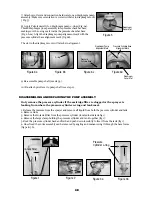
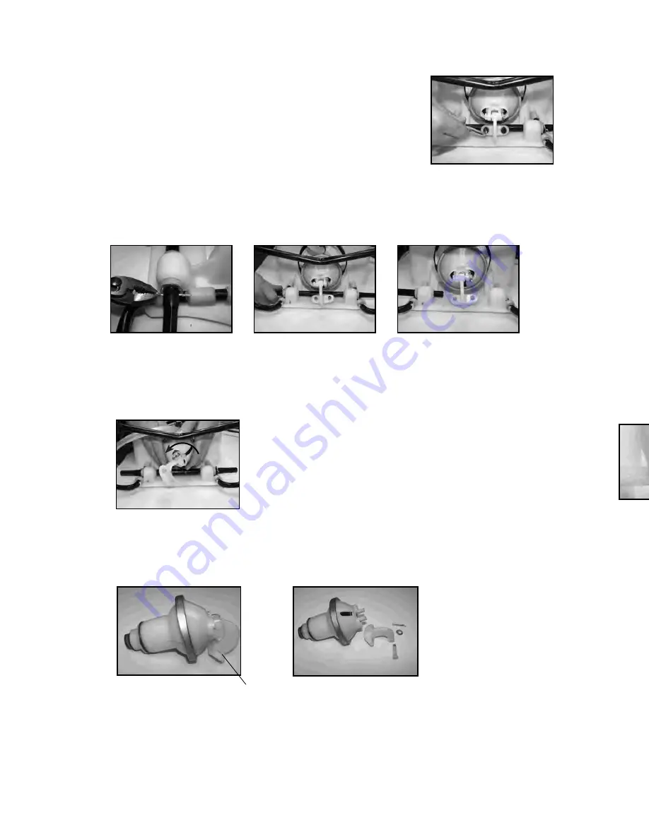
Le nettoyage de la cartouche du filtre de l'étape 3 exige le retrait de tout l'assemblage
du cylindre de pression (voir la section « démonter et réparer le cylindre de
pression »). Lorsque le cylindre de pression est retiré, le filtre de l'étape 3 peut être
retiré pour son nettoyage (voir la Figure 3). Un nettoyage régulier du filtre de l'étape
2 est fortement recommandé et cela réduira le besoin de ce démontage. Il est
préférable d'avoir peu ou aucun fluide dans la cuve avant de retirer et de réinstaller le
filtre de la cuve de l'étape 2. Le tube de filtre doit être orienté d'une certain façon
lorsqu'il est inséré dans la base du cylindre de pression (voir la Figure 2).

Le filtre d'étape 4 est un filtre amovible incorporé du côté d'entrée de robinet d'arrêt
(voir la section « démonter et réparer le robinet d'arrêt »). Assurez-vous que la
pression est retirée avant d'enlever le boyau du robinet. Il est préférable d'avoir peu
ou aucun fluide dans le cylindre de pression avant de retirer et de réinstaller le filtre
d'arrêt de l'étape 4 car le fluide pourrait couler du boyau.

Étape 1

(panier-filtre)

Étape 2

(tube

amovible)

Figure 1

Étape 3 (cartouche

filtre)

Figure 2 Étape 2 (tube à filtre amovible)

Figure 3 Étape 3 (cartouche à filtre amovible)

Cartouche filtre retirée

Cartouche filtre dans la base

du cylindre de pression

Bord-guide face au côté opposé

du cylindre de pression

Bord-guide face sur le

cylindre de pression

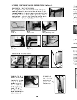
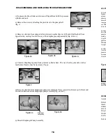
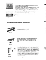
1) De-pressurize the cylinder and remove all liquid from both the pressure
cylinder and tank.

2) Remove the 2 screws attaching the pivot lever to the pump shaft
(fig. 1)

3) Remove cotter pin from pump shaft and remove washer (fig. 2a). Pull and slide the shaft from
opposite side, moving it out of the way of the diaphragm pump assembly (fig. 2b & 2c).

4) Unscrew diaphragm pump from pressure cylinder base. The use of a strap wrench or other
mechanical means may be neccesary (fig. 3).

6) Discard Diaphragm Pump Assembly.

  DISASSEMBLING AND REPLACING THE DIAPHRAGM PUMP

5) Remove cotter pin from diaphragm pump assembly pivot lever connection. Remove pivot lever and
connection hardware from diaphragm pump assembly (Fig. 4a & 4b).

Figure 1

Figure 2a

Figure 4a

Figure 2b

Figure 2c

Figure 4b

Figure 3

Pivot Lever

Connection

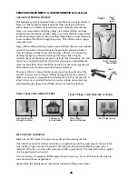
REMPLIR LE PULVÉRISATEUR

Assurez-vous que le panier-filtre est en place pour empêcher les débris d'entrer dans le réservoir.

Déterminez la quantité de mélange nécessaire pour votre application. Ajoutez la bonne quantité d'eau au
réservoir. Ajoutez la bonne quantité de produits chimiques au réservoir (vérifiez l'étiquette des produits
chimiques pour connaître le bon rapport des produits). Remuez le mélange dans le réservoir avec un
accessoire propre (comme un agitateur de peinture). Le réservoir a une capacité de 15 l (4 gallons) en plus
des produits chimiques.

Il n'est pas nécessaire de remplir le réservoir du pulvérisateur à chaque utilisation. Vous pouvez le remplir
en choisissant seulement la quantité nécessaire pour chaque application.

Suivez toujours les instructions du fabricant qui se trouvent sur l'étiquette du produit.

Cylindre de

pression

Summary of Contents for BACKPACK MS-40BD

Page 1: ...011300 R0211 Carefully Read These Instructions Before Use 44100486 usse de t torique WARNING Model MS 40BD 4 0G 15 1L Use and Care Manual Backpack ...

Page 2: ...attached to the shut off assembly Insure hose is securely attached to the tank by tightening hose clamp if necessary Insure that all nozzle and wand connections are tight Insure the large pump clamp is tight Insure the 2 bolts used to attach the pump lever to the pump shaft are tight DO NOT leave a pressurized sprayer in the hot sun or anywhere near a heat source Heat can produce pressure to build...

Page 3: ...same sprayer for plant feeding or protection without thoroughly cleaning see cleaning section the sprayer first General Household Use Apply detergents vinegar cleaning solutions warm water do not exceed 120 F 49 C or nontoxic household cleaning chemicals for carpets floors walls glass counter tops and ceilings DO NOT use sprayer that has been used with herbicides pesticides or other toxic chemical...

Page 4: ...ed to the tank Attach the lower end of the straps by clipping the strap hooks to the metal frame between where the frame exits the tank and curves around WAND CLIP The wand can be attached to the pump handle using the wand clip Figure 1 Cotter Pin Figure 2 Line up holes Figure 3 Slide pin through holes SPRAYER COMPONENTS USE INFORMATION Continued A C B Pull up Rotate 180º Set into slot Pump Handle...

Page 5: ...rayer This will also reduce sprayer component wear Stage 3 filter cartridge cleaning requires removal of the entire pressure cylinder assembly see section disassembling and repairing the pressure cylinder Once the pressure cylinder is removed the stage 3 filter can be removed for cleaning see figure 3 Periodic cleaning of the stage 2 filter is highly recommended and will reduce the need to perform...

Page 6: ...horoughly after each use 2 Pump the sprayer handle until all of the contents and air exit through the nozzle minimum of 30 strokes 3 Fill tank half way with water and pump the water out as explained in step 2 repeat several times as necessary Other Cleaning Hints Improper spray distribution usually means the nozzle is clogged remove the nozzle and clean it Soap can be added to the water to clean t...

Page 7: ...lease pressure in pressure chamber pumping strokes but pressure only lasts chamber Remove the hose drain pressure briefly chamber Reconnect the hose Upper valve plate damaged worn dirty Clean or replace upper valve plate Upward pumping action is more difficult Vent hole is clogged Clear the vent hole in cap and or pump handle moves itself back down Clogged intake filter Clean the In Tank filter an...

Page 8: ...fig 2a Pull and slide the shaft from opposite side moving it out of the way of the diaphragm pump assembly fig 2b 2c 4 Unscrew diaphragm pump from pressure cylinder base The use of a strap wrench or other mechanical means may be neccesary fig 3 6 Discard Diaphragm Pump Assembly DISASSEMBLING AND REPLACING THE DIAPHRAGM PUMP 5 Remove cotter pin from diaphragm pump assembly pivot lever connection Re...

Page 9: ...nection hardware to new diaphragm pump assembly Make sure orientation is correct with slot in diaphragm cover Fig 5 Figure 5 Figure 6d Pressure Cylinder Base Alignment Mark Diaphragm Pump Alignment Mark Diaphragm Cover Slot Figure 6c Pressure Cylinder Base Figure 6b O ring Figure 6a O rings 1 Release the pressure from the sprayer and remove all liquid from both the pressure cylinder and tank 2 Rem...

Page 10: ...filter C in end of shut off valve for debris Remove filter and flush with water to clean out DISASSEMBLING AND REPAIRING THE SHUT OFF VALVE 9E A F D in jo in F D d APPL É p u d N fe H p d U n r N t U d d s INFOR 1 Figure 5 7 At this point the filter cartridge in the pressure chamber base can be removed with pliers and cleaned fig 4 8 The pressure chamber o ring can also be replaced DO NOT stretch ...

Page 11: ...t Fan Nozzle 99944100483 Poly Adjustable Nozzle 99944100482 Brass Adjustable Nozzle Screw Cap O ring 99944100480 Wand Assembly Wand 99944100478 Shut off Assembly 99944100481 Filter Replacement Kit 99944100479 Hose Assembly Hose Washer Retaining Nut Hose 99944100485 Nozzle Kit vre az ns et le oit ue n be e de e ...

Page 12: ...bow O ring Hose Gasket Nozzle Gasket 99944100486 O ring Kit 99944100473 Filter Basket Cap 99944100472 Straps 99944100476 Diaphragm Pump Assembly O ring O ring Plate Valve 99944100489 Pump Handle M d e ECHO INCORPORATED 400 Oakwood Road Lake Zurich IL 60047 www echo usa com ...

Page 13: ...n a piston pump sprayer Wear items including but not limited to seals gaskets pistons hoses diaphragms straps or any wear item These items are covered for 90 days from date of purchase Any mis use of product is not covered including but not limited to using un approved chemicals or parts un approved uses using damaged or missing units parts during operation or modifying your sprayer in any manner ...

Reviews: