background image

In-tank Filter

8E

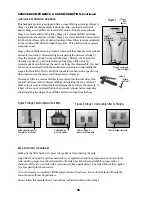
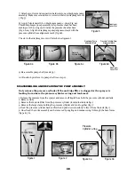
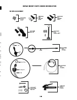
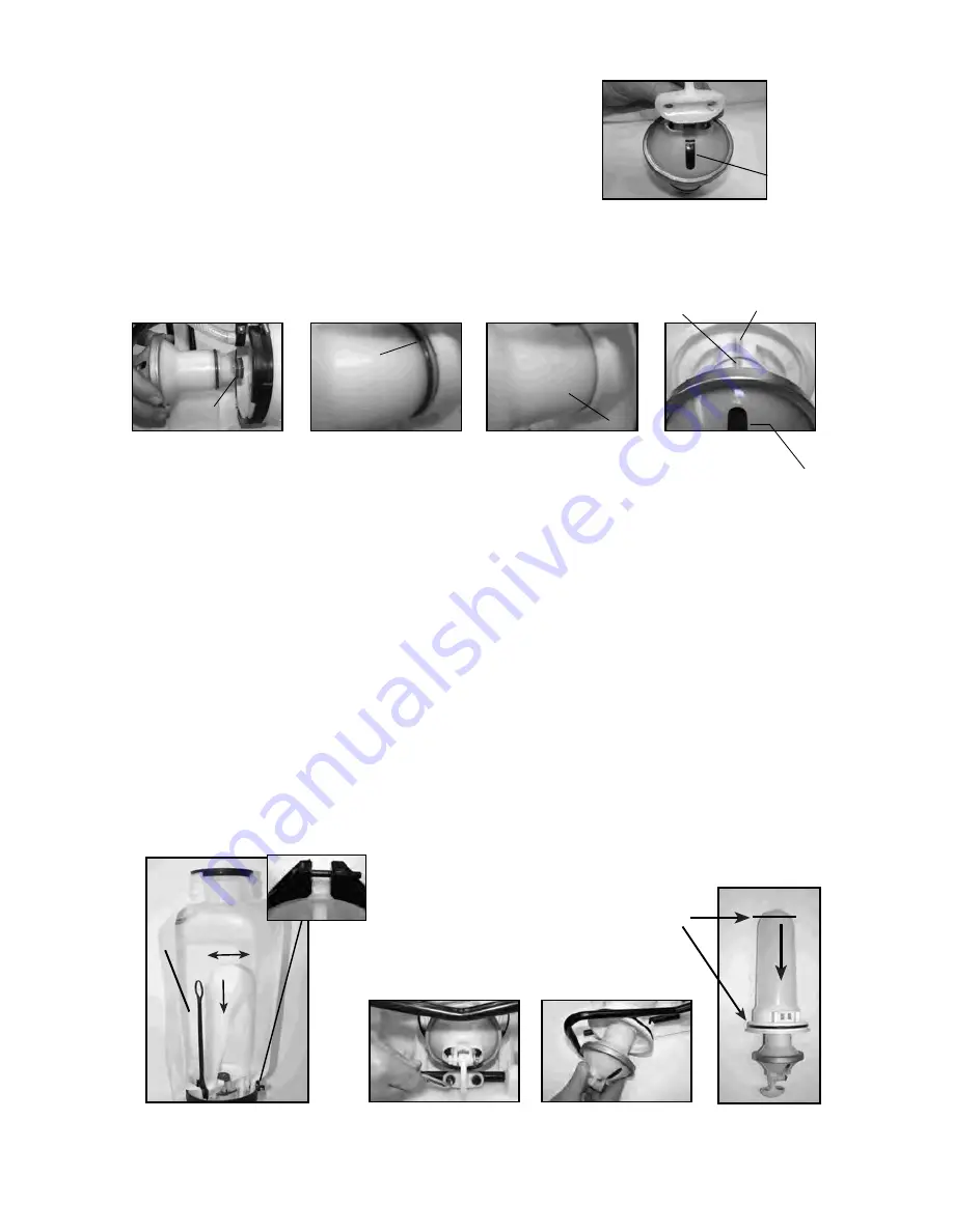
8)  Apply Petroleum jelly to 2 diaphragm pump o-rings (Fig. 6a).
Thread diaphragm pump assembly into pressure chamber base,
making sure the o-ring seats inside the pressure chamber base
(Fig. 6b-6c). Align the diaphragm pump alignment mark with the
pressure cylinder base alignment mark  (fig.6d).

The slot in the diaphragm cover will also be in alignment.

9) Re-assemble pump shaft (see step 3).

10) Re-attach pivot lever to pump shaft (see step 2).

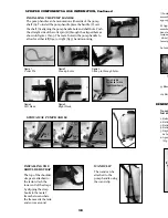
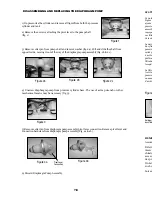
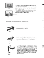
Only remove the pressure cylinder if the cartridge filter  is clogged or the sprayer is
leaking from where the pressure cylinder o-ring and tank meet.

  DISASSEMBLING AND REPAIRING THE PUMP ASSEMBLY

7) Attach pivot lever and connection hardware to new diaphragm pump
assembly. Make sure orientation is correct with slot in diaphragm cover
( Fig. 5).

Figure 5

Figure 6d

Pressure Cylinder Base

Alignment Mark

Diaphragm Pump

Alignment Mark

Diaphragm

Cover Slot

Figure 6c

Pressure

Cylinder Base

Figure 6b

O-ring

Figure 6a

O-rings

1. Release the pressure from the sprayer and remove all liquid from both the pressure cylinder and tank.
2. Remove Hose
3. Remove the In-tank Filter from the pressure cylinder (located inside tank fig 1).
4. Remove the large clamp holding the pressure cylinder and tank together (fig 1).
5. Rock the pressure cylinder back and forth and push down forcefully to free it from the tank (fig 1).
6. Once freed the entire assembly can be removed by angling and maneuvering it through the base frame
(fig 3a & 3b).

Figure 2

Figure 3a

Figure 3b

Pressure

Cylinder o-ring

Diaphragm

Cover Slot

Clamp

Figure 1

3F

INFORMATION D'UTILISATION ET COMPOSANTS DU PULVÉRISATEUR, suite

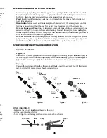
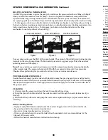
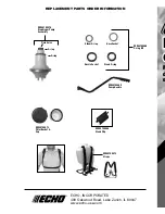
INSTALLER LA POIGNÉE DE POMPE

La poignée de pompe s'installe à l'une ou l'autre extrémité de l'arbre
de la pompe (A). Pour installer la poignée de pompe, placez la
poignée (C) sur l'arbre (A) en alignant le trou de la poignée de pompe
et le trou de l'arbre. Poussez le côté droit de la goupille fendue (B) à
travers le trou aligné tel qu'indiqué dans les figures 1 à 3. Il y a dans
trous dans la poignée de la pompe pour permettre un montage de
gaucher (fig. 4) ou droitier (fig. 5).

INSTALLER LA
BANDOULIÈRE

Le dessus des

bandoulières est fixé à

la cuve. Fixez

l'extrémité inférieure

des bandoulières en

attachant les crochets

de sangle à l'armature

de métal entre l'endroit

où celle-ci sort de la

cuve et où elle se

recourbe.

PINCE DU TUBE

Le tube s'installe à
la poignée de la
pompe en utilisant
la pince du tube.

A

C

B

Relevez

Tournez

de 180º

Placez

dans

la

fente

Pump Handle

Positioned For Use

(right hand shown)

Figure 5

Droitier

Figure 4

Gaucher

POIGNÉE DE POMPE ESCAMOTABLE

Figure 1

Goupille fendue

Figure 2

Alignez les trous

Figure 3

Glissez la goupille à travers les trous.

Summary of Contents for BACKPACK MS-40BD

Page 1: ...011300 R0211 Carefully Read These Instructions Before Use 44100486 usse de t torique WARNING Model MS 40BD 4 0G 15 1L Use and Care Manual Backpack ...

Page 2: ...attached to the shut off assembly Insure hose is securely attached to the tank by tightening hose clamp if necessary Insure that all nozzle and wand connections are tight Insure the large pump clamp is tight Insure the 2 bolts used to attach the pump lever to the pump shaft are tight DO NOT leave a pressurized sprayer in the hot sun or anywhere near a heat source Heat can produce pressure to build...

Page 3: ...same sprayer for plant feeding or protection without thoroughly cleaning see cleaning section the sprayer first General Household Use Apply detergents vinegar cleaning solutions warm water do not exceed 120 F 49 C or nontoxic household cleaning chemicals for carpets floors walls glass counter tops and ceilings DO NOT use sprayer that has been used with herbicides pesticides or other toxic chemical...

Page 4: ...ed to the tank Attach the lower end of the straps by clipping the strap hooks to the metal frame between where the frame exits the tank and curves around WAND CLIP The wand can be attached to the pump handle using the wand clip Figure 1 Cotter Pin Figure 2 Line up holes Figure 3 Slide pin through holes SPRAYER COMPONENTS USE INFORMATION Continued A C B Pull up Rotate 180º Set into slot Pump Handle...

Page 5: ...rayer This will also reduce sprayer component wear Stage 3 filter cartridge cleaning requires removal of the entire pressure cylinder assembly see section disassembling and repairing the pressure cylinder Once the pressure cylinder is removed the stage 3 filter can be removed for cleaning see figure 3 Periodic cleaning of the stage 2 filter is highly recommended and will reduce the need to perform...

Page 6: ...horoughly after each use 2 Pump the sprayer handle until all of the contents and air exit through the nozzle minimum of 30 strokes 3 Fill tank half way with water and pump the water out as explained in step 2 repeat several times as necessary Other Cleaning Hints Improper spray distribution usually means the nozzle is clogged remove the nozzle and clean it Soap can be added to the water to clean t...

Page 7: ...lease pressure in pressure chamber pumping strokes but pressure only lasts chamber Remove the hose drain pressure briefly chamber Reconnect the hose Upper valve plate damaged worn dirty Clean or replace upper valve plate Upward pumping action is more difficult Vent hole is clogged Clear the vent hole in cap and or pump handle moves itself back down Clogged intake filter Clean the In Tank filter an...

Page 8: ...fig 2a Pull and slide the shaft from opposite side moving it out of the way of the diaphragm pump assembly fig 2b 2c 4 Unscrew diaphragm pump from pressure cylinder base The use of a strap wrench or other mechanical means may be neccesary fig 3 6 Discard Diaphragm Pump Assembly DISASSEMBLING AND REPLACING THE DIAPHRAGM PUMP 5 Remove cotter pin from diaphragm pump assembly pivot lever connection Re...

Page 9: ...nection hardware to new diaphragm pump assembly Make sure orientation is correct with slot in diaphragm cover Fig 5 Figure 5 Figure 6d Pressure Cylinder Base Alignment Mark Diaphragm Pump Alignment Mark Diaphragm Cover Slot Figure 6c Pressure Cylinder Base Figure 6b O ring Figure 6a O rings 1 Release the pressure from the sprayer and remove all liquid from both the pressure cylinder and tank 2 Rem...

Page 10: ...filter C in end of shut off valve for debris Remove filter and flush with water to clean out DISASSEMBLING AND REPAIRING THE SHUT OFF VALVE 9E A F D in jo in F D d APPL É p u d N fe H p d U n r N t U d d s INFOR 1 Figure 5 7 At this point the filter cartridge in the pressure chamber base can be removed with pliers and cleaned fig 4 8 The pressure chamber o ring can also be replaced DO NOT stretch ...

Page 11: ...t Fan Nozzle 99944100483 Poly Adjustable Nozzle 99944100482 Brass Adjustable Nozzle Screw Cap O ring 99944100480 Wand Assembly Wand 99944100478 Shut off Assembly 99944100481 Filter Replacement Kit 99944100479 Hose Assembly Hose Washer Retaining Nut Hose 99944100485 Nozzle Kit vre az ns et le oit ue n be e de e ...

Page 12: ...bow O ring Hose Gasket Nozzle Gasket 99944100486 O ring Kit 99944100473 Filter Basket Cap 99944100472 Straps 99944100476 Diaphragm Pump Assembly O ring O ring Plate Valve 99944100489 Pump Handle M d e ECHO INCORPORATED 400 Oakwood Road Lake Zurich IL 60047 www echo usa com ...

Page 13: ...n a piston pump sprayer Wear items including but not limited to seals gaskets pistons hoses diaphragms straps or any wear item These items are covered for 90 days from date of purchase Any mis use of product is not covered including but not limited to using un approved chemicals or parts un approved uses using damaged or missing units parts during operation or modifying your sprayer in any manner ...

Reviews: